Solar Power Plant Transformers: Engineering Blueprint, Multi-Winding Inverter Integration & Global Procurement Benchmarks
A comprehensive technical guide for EPC contractors, power utilities, and global project developers. Explore solar inverter duty transformer design, harmonic current suppression, extreme thermal load cycling, multi-winding configurations up to 33kV class, and energy efficiency compliance standards.
Understanding Solar Power Plant Transformers: Why Standard Grid Transformers Fail in PV Applications
In modern utility-scale solar photovoltaic (PV) power plants, the transformer is the critical link bridging low-voltage DC-to-AC solar inverters with high-voltage regional transmission grids. However, a common mistake committed by procurement teams during project feasibility phases is treating a Solar Power Plant Transformer as a conventional distribution or step-up power transformer.
Standard distribution transformers are designed for continuous sinusoidal AC loads with predictable power factors and stable ambient thermal environments. In stark contrast, Solar Inverter Duty Transformers operate under severe operational stressors unique to renewable energy generation, including high-frequency pulse-width modulation (PWM) harmonics, DC bias currents injected by solar inverters, rapid daily thermal cycling, and non-uniform solar irradiation curves.
01
Harmonic Current Mitigation
Solar inverters generate significant high-frequency harmonics (3rd, 5th, 7th, and higher order PWM frequencies). Without high K-factor core design and electrostatic shielding, these harmonics induce severe eddy current losses, localized hot-spots, and accelerated insulation breakdown.
02
Extreme Daily Thermal Cycling
Solar transformers experience zero load at night, rapid ramp-up during morning sunrise, peak overload during solar noon, and steep ramp-down at dusk. This repetitive thermal expansion and contraction puts immense mechanical fatigue on winding insulation and tank seals.
03
DC Bias & Offset Currents
Inverter switching asymmetry can inject small DC offset components into the transformer secondary windings. Even low DC currents cause core saturation, leading to increased magnetizing currents, elevated acoustic noise, and extreme no-load losses.
Multi-Winding Architecture: Optimizing Balance of Plant (BOP) CAPEX
To maximize plant yield and reduce land footprint, modern solar central inverter stations combine multiple high-capacity inverters into a single transformer enclosure. Sahara Transformers custom-engineers Multi-Winding Solar Inverter Duty Transformers featuring Dual-Secondary (3-winding), Triple-Secondary (4-winding), and Quad-Secondary (5-winding) configurations.
By isolating multiple inverter outputs through separate low-voltage (LV) windings while stepping up power to a single high-voltage (HV) output at 11kV, 22kV, or 33kV, utility developers achieve up to a 25% reduction in substation cabling, switchgear, and civil foundation costs. However, multi-winding design requires tight impedance matching between secondary windings to prevent circulating cross-inverter fault currents and maintain voltage stability across independent inverter channels.
Sahara Engineering Standard
Manufactured in Pune, India | Serving Global Utilities Since 2007
Strict compliance with IEC 60076-11, IEC 60076-16 & IS 2026 standards
High-grade CRGO steel core with step-lap miter joints for ultra-low losses
Copper grounding shield between HV & LV to divert inverter switching noise
100% Routine Factory Acceptance Testing (FAT) with impulse withstand capability
Recommended Product Range
Utility & Commercial Solar Power Plant Transformers
Engineered specifically for solar step-up applications up to 10 MVA and 33kV class. Compliant with international grid-code requirements and energy efficiency norms.
Solar Inverter DutyUp to 10 MVAMulti-Winding33kV Class
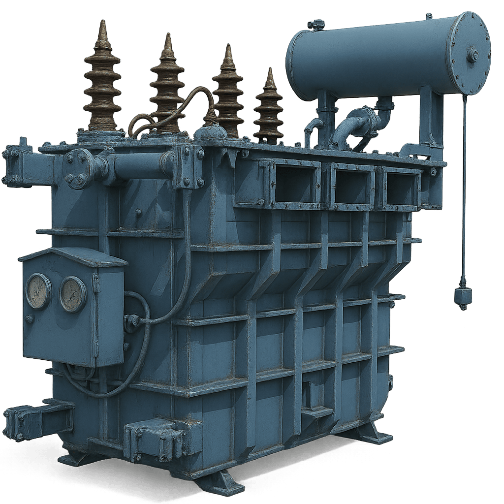
Solar Inverter Duty Transformers (Oil-Immersed)
Specially engineered to step up low-voltage inverter outputs (315V to 800V AC) to medium-voltage collector grids (11kV, 22kV, 33kV). Features multi-secondary windings, electrostatic shielding, and low-loss CRGO laminated cores to handle severe inverter harmonics and continuous outdoor duty cycles.
Custom K-factor rating (K-4, K-9, K-13) for harmonic protection
Dual, Triple, or Quad LV winding designs for multi-inverter inputs
Optional Natural or Synthetic Ester Fluid filling for fire safety & eco compliance
Power TransformerMain SubstationOLTC / DETC33kV Grid Tie
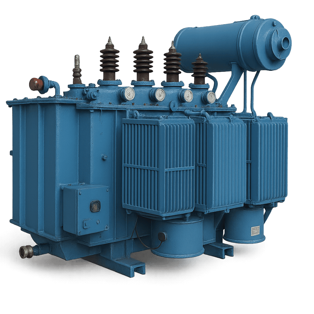
Utility Solar Step-Up Power Transformers
Heavy-duty power step-up units designed for main solar plant pooled substations. Steps up 11kV or 33kV solar array collector busbars to high-voltage regional transmission grids. Built with robust mechanical short-circuit strength and automated On-Load Tap Changers (OLTC) for seamless grid voltage regulation.
High dynamic short-circuit withstand capacity
Low no-load losses for maximum nighttime energy conservation
Integrated Buchholz relays, OTI/WTI sensors & Nitrogen Injection Fire Protection
Dry Type / Cast ResinClass F / H InsulationZero Fire HazardRooftop Solar
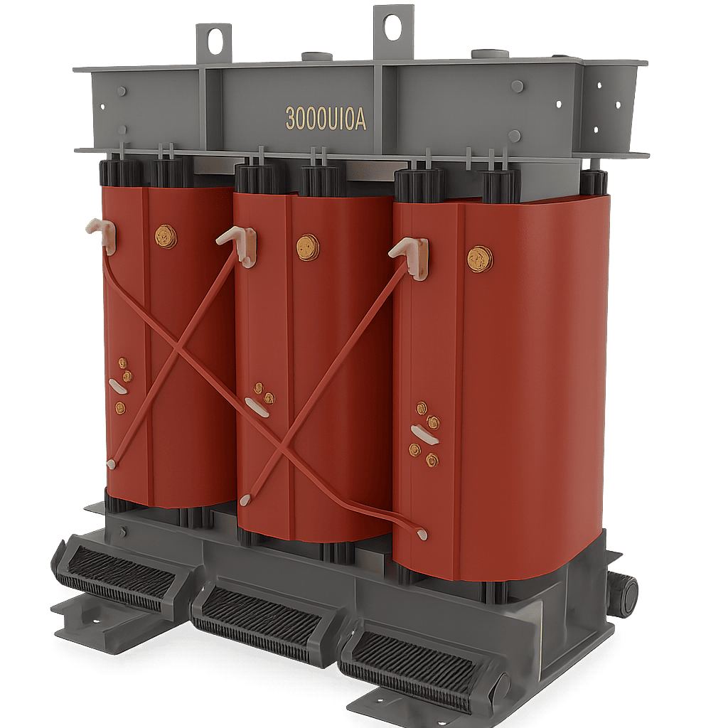
Cast Resin Dry-Type Solar Inverter Duty Transformers
Ideal for commercial rooftop solar projects, floating solar platforms, and indoor solar inverter stations where liquid cooling is restricted due to environmental or fire safety regulations. Epoxy resin vacuum-cast windings ensure complete protection against moisture, dust, and corrosive industrial environments.
Self-extinguishing with F1 fire behavior rating
Maintenance-free operation without oil testing or filtration
High short-time overload capability during peak solar irradiance
Compact SubstationSolar Skid UnitPlug & PlaySF6 Ring Main Unit
Integrated Solar Skid Substation (CSS) Solutions
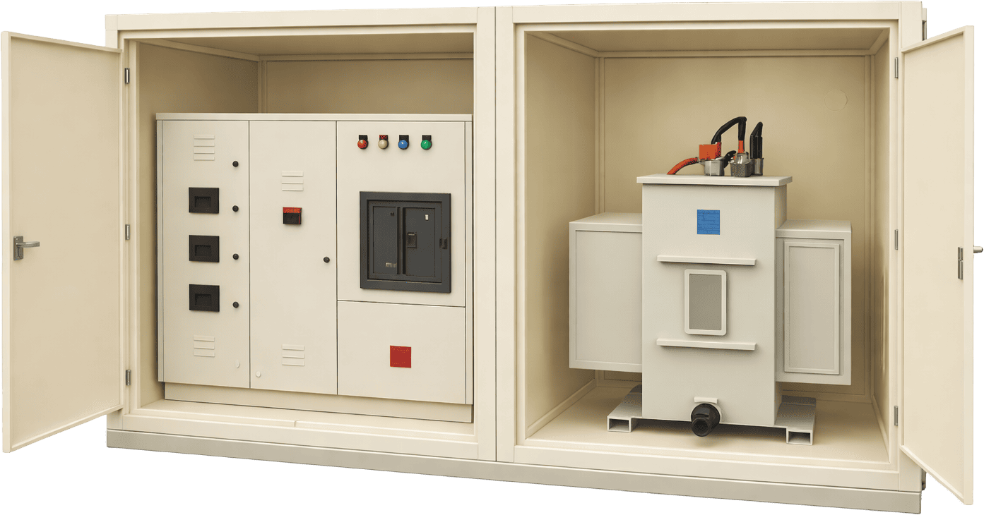
Factory-assembled, plug-and-play outdoor substations combining a Solar Inverter Duty Transformer, High-Voltage SF6 Ring Main Unit (RMU), and Low-Voltage Switchgear into a single weather-proof enclosure. Designed to accelerate field installation times for solar farm block arrays.
Significantly reduces on-site civil works and cable trenching cost
IP54 / IP55 rated enclosure for extreme desert & coastal solar sites
Whether you are designing a 5 MW commercial rooftop array or a 500 MW utility solar farm, Sahara Transformers provides tailored engineering solutions including dual-voltage primary ratios, customized vector groups (Dy11, Dy11y11, Dy5), special impedance values, and smart monitoring instrumentation.
Future Procurement Trends in Utility-Scale Solar Power Plant Transformers (2025–2035)
The global solar energy landscape is undergoing a massive shift towards higher system voltages, larger central inverter blocks, hybrid energy storage systems, and stringent environmental sustainability standards. Procurement directors and EPC engineers must account for five pivotal industry trends shaping the next generation of Solar Power Plant Transformers:
1. Transition to 33kV & 66kV Collector Architectures
To reduce I²R transmission losses over expansive solar farm acreage, global utility developers are transitioning from traditional 11kV collector networks to 33kV and 66kV collector grids. Procurement specifications now mandate higher impulse withstand levels (BIL) and reinforced dielectric insulation capable of withstanding grid switching surges in high-voltage collector rings.
2. Adoption of Eco-Friendly Natural & Synthetic Ester Fluids
Mineral oil transformer leaks pose environmental contamination risks in agricultural and floating solar sites. Modern solar tenders increasingly specify Natural Ester (Vegetable Oil) or Synthetic Ester Fluids. Ester fluids offer a fire point >300°C (K-class non-flammable), high biodegradability (>99% in 28 days), and high moisture tolerance, effectively doubling cellulose insulation lifespan.
3. BESS-Integrated Hybrid Transformers
With the rapid integration of Battery Energy Storage Systems (BESS) alongside PV plants, transformers must handle bi-directional power flow. Inverter duty transformers are now engineered to step up solar power during peak generation hours while stepping down grid power during night cycles for battery charging, requiring specialized tap-changer dynamics and thermal management.
Procurement frameworks now demand online transformer health diagnostics to prevent unscheduled outages in remote solar installations. Integrated sensors continuously transmit Dissolved Gas Analysis (DGA), fiber-optic winding hotspot temperatures, oil moisture levels, and bushing power factor data directly to plant SCADA and cloud-based AI maintenance platforms.
Technical Parameter Comparison: Standard Distribution vs. Solar Inverter Duty Transformer
The following technical matrix highlights the core structural and operational engineering differences that procurement teams must evaluate when sourcing step-up transformers for PV applications:
Engineering Parameter
Standard Distribution / Power Transformer
Solar Inverter Duty Transformer (Sahara Standard)
Primary Load Profile
Continuous, steady-state sinusoidal 50/60 Hz AC load
Pulsating DC-to-AC non-sinusoidal load with high solar cyclic variation
Harmonic Tolerance (K-Factor)
Standard K-1 rating (minimal harmonic current allowance)
High K-Factor rated (K-4, K-9, K-13+) with extra copper cross-section
LV Windings / Inputs
Single Low Voltage (LV) winding input
Multi-Winding (Dual, Triple, or Quad LV windings isolated electrically)
Electrostatic Shielding
Not required in standard utility distribution
Mandatory grounded copper shield between HV & LV to block PWM high-frequency noise
No-Load Loss Optimization
Standard utility loss limits (IS 1180 Level 1 / Level 2)
Ultra-low no-load losses (CRGO laser-scribed core) for zero daytime standby waste
Thermal Stress Tolerance
Designed for gradual load variation
Reinforced winding clamping structure for rapid daily thermal expansion cycles
Cooling Medium
Standard Mineral Oil (ONAN/ONAF)
High Fire-Point Synthetic/Natural Ester Fluid or Cast Resin (FR3 / Ester optional)
R&D & Manufacturing Innovation
Technology Development Trends in Solar Power Plant Transformer Manufacturing
As solar power plants scale into multi-gigawatt utility hubs, transformer manufacturers are driving breakthrough innovations in core metallurgy, winding geometry, dielectric insulation, and thermal modeling. At Sahara Transformers, our R&D center in Pune continuously integrates advanced manufacturing techniques to address the evolving demands of global solar developers:
Laser-Scribed CRGO & Amorphous Core Metallurgy
To eliminate high idle-power consumption during cloudy weather and nighttime hours, we utilize high-permeability, domain-refined laser-scribed Cold Rolled Grain Oriented (CRGO) steel and Amorphous Metal alloys. This reduces core hysteresis losses by up to 30% compared to standard core steel laminations.
Finite Element Method (FEM) Thermal & Stray Field Analysis
Harmonic currents cause eddy current hot-spots in transformer tank walls and structural clamping frames. Using 3D Finite Element Method (FEM) software, our design engineers optimize winding conductor transposed cables (CTC) and magnetic shielding, ensuring uniform heat dissipation under 110% continuous inverter overloading.
Extended Mechanical Short-Circuit Rigidity
Solar inverters experience frequent cloud transients and grid fault ride-through (FRT) events. Our transformer coils undergo high-pressure hydraulic compaction and hot-vacuum drying (VPD), resulting in exceptionally high axial and radial mechanical rigidity capable of withstanding severe short-circuit electromagnetic forces.
Accelerate Your Solar Infrastructure Project with Sahara Engineers
Custom design specifications, detailed CAD layout drawings, loss calculations, and competitive pricing available for global EPC tenders and procurement teams.
Frequently Asked Technical Questions on Solar Power Plant Transformers
Below are comprehensive answers to high-intent questions frequently queried by global procurement managers, EPC system integrators, and solar power project consultants when selecting inverter duty step-up transformers:
What is the difference between a standard power transformer and a solar inverter duty transformer?
A standard power transformer steps up grid voltage for pure 50Hz or 60Hz AC sine wave currents. A Solar Inverter Duty Transformer is specifically engineered to interface with solar PV inverters. Inverters output non-sinusoidal waveforms containing pulse-width modulation (PWM) high-frequency harmonics and potential DC offset components.
Solar inverter duty transformers incorporate high K-factor rated winding conductors, electrostatic copper shields between primary and secondary windings to divert switching noise to ground, extra insulation allowances for voltage spikes, and multi-secondary winding configurations (dual, triple, or quad LV inputs) to step up power from multiple central inverters simultaneously.
How do multi-winding configurations (dual vs quad secondary) optimize solar farm CAPEX?
Multi-winding solar transformers feature two, three, or four separate low-voltage (LV) secondary windings on a single magnetic core, all stepping up to a single high-voltage (HV) primary output (e.g., 33kV).
This multi-input design allows 2 to 4 central solar inverters to connect directly to one transformer instead of installing individual transformers for every inverter. This reduces total transformer unit count, minimizes footprint on solar skids, cuts medium-voltage switchgear requirements, and lowers balance of plant (BOP) installation costs by up to 25%.
How do you calculate K-factor and derating factors for transformers connected to central solar inverters?
The K-factor measures a transformer’s ability to handle non-sinusoidal harmonic load currents without exceeding temperature rise limits. K-factor is calculated based on the harmonic spectrum provided by the inverter manufacturer using the formula: K = ∑ (I_h / I_1)² × h², where h is the harmonic order and I_h is the RMS current at harmonic h.
For central solar inverters, K-4 to K-13 ratings are typical. If a standard transformer is used without K-factor sizing, it must be derated by 15% to 35% of its rated capacity to prevent thermal damage from eddy current heating. Sahara Transformers designs custom-wound coils that operate at 100% full rating under specified inverter harmonic profiles without thermal derating.
What compliance standards govern Solar Power Plant Transformers internationally?
Solar power plant transformers manufactured by Sahara Transformers comply with major international and regional standards, including:
IEC 60076-16: Power transformers - Part 16: Transformers for wind turbine and solar PV application
IEC 60076-11: Dry-type transformers for indoor/rooftop solar stations
IEEE C57.159: IEEE Guide for Application of Transformers in Distributed Photovoltaic (DPV) Generation Systems
IS 2026 / IS 1180: Indian Standards for power and distribution transformers with energy efficiency loss limits
ISO 9001:2015 & ISO 14001: Quality and environmental manufacturing management systems
Why is electrostatic shielding mandatory between primary and secondary windings in PV transformers?
High-frequency switching in solar inverters creates common-mode voltage transients and high dV/dt voltage spikes. An electrostatic shield—consisting of a grounded copper sheet placed between the HV and LV windings—acts as a capacitive barrier.
It safely diverts high-frequency switching noise, electromagnetic interference (EMI), and surge transients directly to earth ground. This prevents high-frequency noise from transferring into the high-voltage collector grid, protecting grid power quality and safeguarding sensitive electronic controls inside the inverter.
How does daily solar thermal cycling affect transformer life, and how is it mitigated?
Unlike industrial base-load transformers that operate at steady load, solar transformers cycle from 0% load at night to 100%+ load at peak irradiance times daily. This constant heating and cooling causes cyclical thermal expansion and contraction in paper insulation, copper windings, tank radiators, and gasketing.
Sahara Transformers mitigates thermal fatigue by employing thermally toughened Kraft paper, high-density pressboard insulation, flexible corrugated tank radiators or detachable radiators with high-grade fluoro-elastomer (Viton) gaskets, and ONAN/ONAF cooling configurations engineered for peak ambient temperatures up to 55°C.
What total loss limits apply under energy efficiency guidelines for solar step-up transformers?
Energy efficiency standards such as IS 1180 (Part 1) Amendment 1 and IEC 60076-20 prescribe maximum allowable 50% load and 100% load total loss figures. For solar power plants, minimizing No-Load Losses (Core Losses) is especially critical because the transformer remains energized from the HV grid during non-generating night hours.
By utilizing high-grade CRGO laminations with precision 45-degree mitered step-lap joints, Sahara transformers achieve ultra-low core losses, ensuring maximum net energy yield (kWh) transferred to the grid across the 25-year asset lifecycle.
What factory acceptance testing (FAT) is critical before dispatching a solar transformer?
Before shipment, every Sahara Solar Transformer undergoes rigorous routine and type testing at our testing laboratory in accordance with IEC 60076:
Measurement of winding resistance, voltage ratio, and vector group verification
Measurement of impedance voltage, short-circuit impedance, and load loss
Measurement of no-load loss and core magnetizing current
Separate-source AC withstand voltage testing and Induced Overvoltage Withstand test
Lightning Impulse Voltage Withstand Test (Full Wave & Chopped Wave)
Dissolved Gas Analysis (DGA) and dielectric Breakdown Voltage (BDV) testing of insulating liquid
Why Choose Sahara Transformers
Engineering Excellence & Global Manufacturing Authority
Established in 2007 in Pune, India, Sahara Transformers is an ISO-certified manufacturer specializing in high-reliability power, distribution, dry-type, and specialized solar duty transformers.
17+ Years
Proven Operational Reliability
Over 17 years of specialized manufacturing experience delivering custom transformers to utilities, heavy industrial plants, EPC contractors, and global solar developers.
ISO Certified
Stringent Quality Standards
ISO 9001:2015 certified production processes ensuring complete traceability from raw copper wire procurement to final pressure leak testing and routine FAT.
Up to 10 MVA
High Voltage Customization
Complete engineering capability to build oil-immersed and dry-type cast resin units up to 10 MVA capacity and 33kV voltage class tailored to specific solar project requirements.
Ready to Source High-Performance Solar Power Plant Transformers?
Connect directly with our engineering sales team in Pune, India. Receive comprehensive product catalogs, technical datasheets, impedance profiles, and project quotation assistance.