11kV Energy Efficient Transformers: Comprehensive Global Procurement, Technical Evaluation, and TCO Optimization Guide

An authoritative engineering whitepaper and buyer benchmark for specifying, purchasing, and evaluating high-efficiency 11kV distribution and step-down transformers. Optimized for industrial utilities, EPC contractors, and global power system engineers seeking maximum information gain, lifecycle cost reduction, and carbon neutrality.

IS 1180 (Part 1) Level 1, 2 & 3 Compliant
IEC 60076 & EU EcoDesign Tier 2 Ready
Proven TCO & Lifecycle Payback Models
Contact Us Explore TCO Model

The Engineering Foundation of 11kV Energy Efficient Transformers

Energy efficiency in medium-voltage (MV) electrical distribution networks has evolved from a voluntary sustainability goal to a strictly enforced global mandate. Within modern power grids, industrial plants, renewable parks, and commercial infrastructure, 11kV Energy Efficient Transformers represent the vital linkage between high-voltage transmission grids and localized step-down consumption. Operating continuously for 20 to 30 years, transformer internal losses account for up to 3% of total generated electrical energy globally. Minimizing these losses through advanced magnetic domain refining, precision core mitring, and low-resistance copper windings directly transforms operational expenditure into long-term enterprise profitability.

To evaluate an 11kV transformer's true efficiency, power systems engineers separate energy dissipation into two primary physics-based components: No-Load Losses (Core Losses, $P_0$) and Load Losses (Copper/Winding Losses, $P_k$).

1. No-Load Losses ($P_0$ / Hysteresis & Eddy Current)

No-load losses occur whenever the transformer is energized, regardless of whether it is feeding a load. Caused by magnetic hysteresis in the core laminations and induced eddy currents within the iron structure, $P_0$ remains constant 24 hours a day, 365 days a year. Energy-efficient designs utilize laser-scribed Cold Rolled Grain Oriented (CRGO) silicon steel or Amorphous metal alloys to restrict hysteresis loops and eliminate micro-eddy pathways, reducing continuous baseline power draw by up to 40%.

2. Load Losses ($P_k$ / Winding & Stray Losses)

Load losses vary quadratically with the transformer load current ($I^2R$). They comprise primary and secondary copper winding resistance loss, stray flux loss in structural tank walls, and eddy losses within conductor strands. High-efficiency 11kV transformers employ high-purity (99.99% conductivity) electrolytic copper conductors, continuously transposed conductors (CTC) for high kVA ratings, and optimized step-lap core geometries to eliminate localized hotspot heating and stray flux coupling.

Global standardization bodies have codified these physics parameters into rigorous efficiency thresholds. In India, the Bureau of Energy Efficiency (BEE) and Bureau of Indian Standards (BIS) govern 11kV class transformers under IS 1180 (Part 1): 2014 and its subsequent Amendment No. 1, categorizing units into Energy Efficiency Level 1, Level 2, and the ultra-low loss Level 3. Internationally, these standards align with IEC 60076-20, EU EcoDesign Directive Tier 2 (EN 50588-1), and IEEE C57.12.00 standards.

IS 1180 (Part 1): 2014 Maximum Total Loss Benchmark

Comprehensive loss allocation thresholds for 11kV step-down distribution transformers up to 2500 kVA. Evaluating 50% and 100% loading parameters across Energy Efficiency Levels 1, 2, and 3.

Sl. No. Rating (kVA) Impedance (%) Maximum Total Loss Allowed (Watts)
Energy Efficiency Level 1 Energy Efficiency Level 2 Energy Efficiency Level 3 (Highest Efficiency)
50% Load 100% Load 50% Load 100% Load 50% Load 100% Load
i250 kVA4.501050 W3150 W980 W2930 W920 W2700 W
ii315 kVA4.501100 W3275 W1025 W3100 W955 W2750 W
iii400 kVA4.501300 W3875 W1225 W3450 W1150 W3330 W
iv500 kVA4.501600 W4750 W1510 W4300 W1430 W4100 W
v630 kVA4.502000 W5855 W1860 W5300 W1745 W4850 W
vi800 kVA5.002459 W7300 W2287 W6402 W2147 W5837 W
vii1000 kVA5.003000 W9000 W2790 W7700 W2620 W7000 W
viii1250 kVA5.003600 W10750 W3300 W9200 W3220 W8400 W
ix1600 kVA6.254500 W13500 W4200 W11800 W3970 W11300 W
x2000 kVA6.255400 W17000 W5050 W15000 W4790 W14100 W
xi2500 kVA6.256500 W20000 W6150 W18500 W5900 W17500 W

Looking for bespoke primary voltage ratios (e.g., 11kV to 3.3kV, 11kV to 415V, or 11kV to 690V) with custom impedance specs? Talk to our engineering desk directly.

Contact Us

Total Cost of Ownership (TCO) & Capitalized Loss Formulas

Procurement departments that select 11kV transformers solely based on Lowest Purchase Price (CAPEX) incur massive hidden financial penalties over the transformer's operating lifespan. Because an 11kV transformer consumes electricity continuously for 25+ years, the cost of wasted energy routinely exceeds the initial purchase price by 300% to 500%.

To evaluate suppliers objectively, global utility buyers and industrial procurement teams utilize the Capitalized Total Cost of Ownership (TCO) methodology:

The Capitalized Loss TCO Formula

The capitalized cost of transformer ownership is calculated using the standard IEEE/IEC loss valuation equation:

TCO = CAPEX + (A × P_0) + (B × P_k)

Where:

  • CAPEX: Initial capital purchase price including delivery, taxes, and installation.
  • $P_0$: Guaranteed No-Load Loss in Kilowatts (kW).
  • $P_k$: Guaranteed Load Loss in Kilowatts (kW) at rated current and reference temperature (75°C).
  • A ($/kW): Capitalized value of No-Load Loss over the operating lifecycle ($A = \frac{\text{Electricity Cost (\$/kWh)} \times 8760 \text{ hrs/yr} \times [(1+i)^n - 1]}{i(1+i)^n}$).
  • B ($/kW): Capitalized value of Load Loss, adjusted for expected average loading factor ($L$) ($B = A \times L^2$).

Real-World Economic Comparison: Standard vs. Energy Efficient 1000 kVA 11kV Transformer

Consider a continuous-duty manufacturing plant operating a 1000 kVA, 11kV/433V distribution transformer at an average 70% load factor over a 20-year lifespan. Electricity tariff is estimated at a conservative $0.12 per kWh.

Standard Legacy Unit (Pre-Regulatory Standard)

  • CAPEX: $14,000
  • No-Load Loss ($P_0$): 1.80 kW
  • Load Loss ($P_k$ at 100%): 10.50 kW
  • Annual Energy Loss: 47,880 kWh
  • 20-Year Cumulative Energy Cost: $114,912
  • Total Lifecycle Cost (TCO): $128,912

Sahara IS 1180 Level 3 Energy Efficient Unit

  • CAPEX: $18,500
  • No-Load Loss ($P_0$): 0.95 kW
  • Load Loss ($P_k$ at 100%): 7.00 kW
  • Annual Energy Loss: 29,740 kWh
  • 20-Year Cumulative Energy Cost: $71,376
  • Total Lifecycle Cost (TCO): $89,876

The Financial Verdict: Although the Level 3 Energy Efficient transformer requires a $4,500 higher upfront CAPEX, it yields $43,536 in net energy savings over 20 years. The simple ROI payback period is achieved in under 26 months of continuous operation, while simultaneously eliminating over 320 Metric Tons of CO2 equivalent emissions.

11kV Energy Efficient Product Recommendations

Engineered at our state-of-the-art Pune facility. Every product line is custom designed to satisfy specific industrial loading profiles, severe ambient conditions, and international standards.

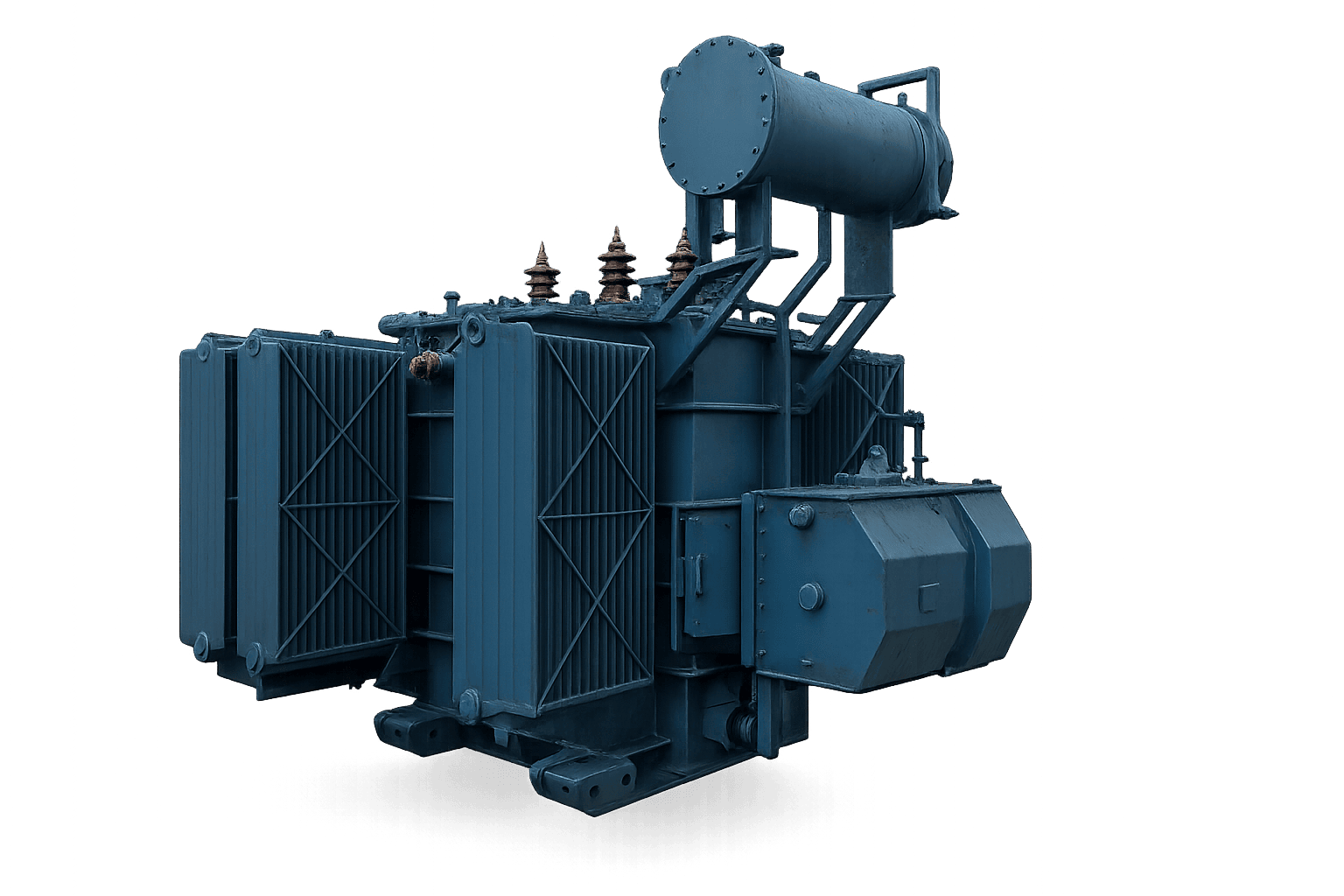
11kV High Efficiency Power Transformer by Sahara Transformers

11kV High-Efficiency Power Transformers

Built for heavy industrial substations, regional power utilities, and bulk generation step-up applications. Features step-lap mitred CRGO core construction, multi-layer helical windings, and low-noise tank designs with high short-circuit withstand capabilities.

Capacity Range: Up to 10 MVA, 33kV Class
Efficiency Compliance: IS 2026, IEC 60076, IEEE C57
Contact Us
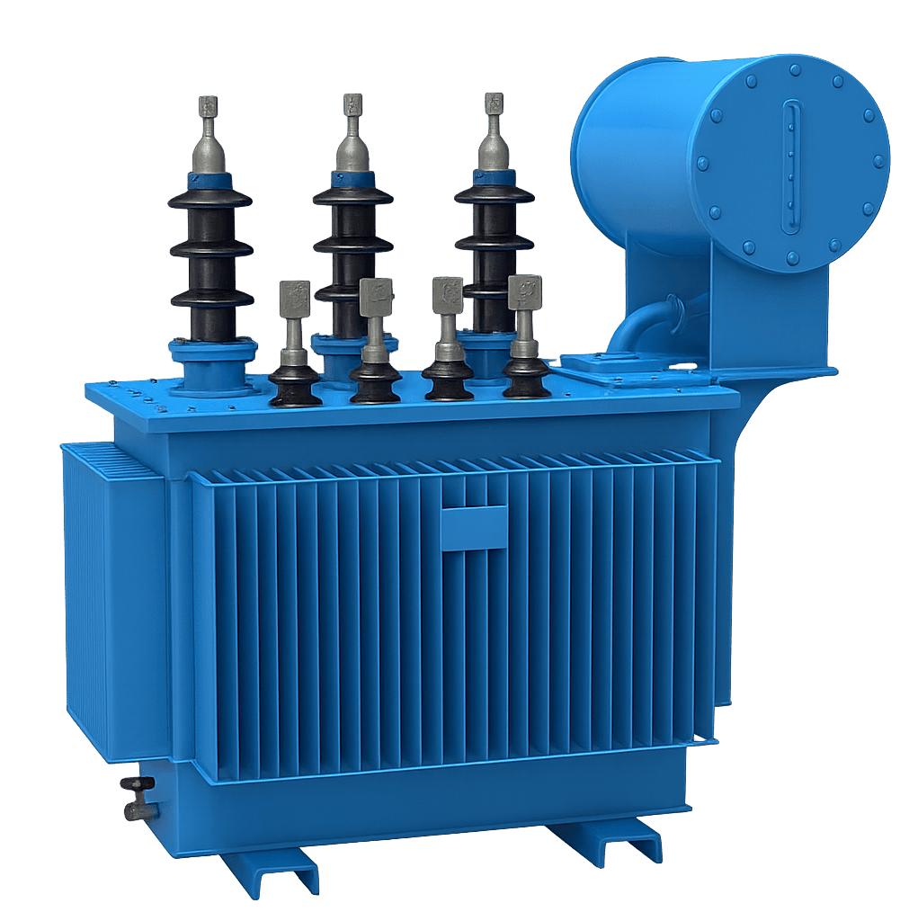
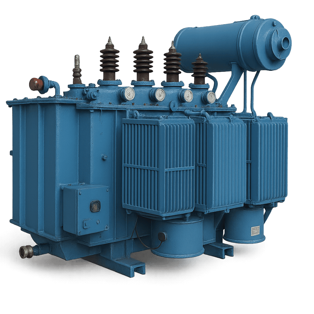
11kV Energy Efficient Distribution Transformer by Sahara Transformers

11kV Energy Efficient Distribution Transformers

Optimized for city power grids, industrial parks, and commercial complexes. Precision engineered to meet IS 1180 Level 2 and Level 3 energy efficiency ratings, drastically lowering continuous distribution losses.

Capacity Range: 25 kVA to 2500 kVA (11kV Step-Down)
Cooling Type: ONAN / ONAF Oil-Immersed
Contact Us
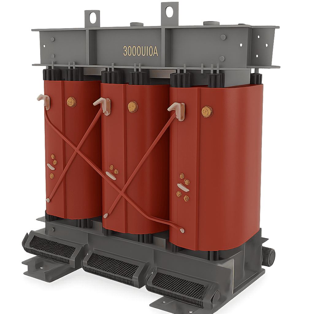
11kV Dry Type Cast Resin Transformer CRT

11kV Dry-Type Cast Resin Transformers (CRT)

Designed for indoor installations, high-rise buildings, data centers, and underground metro networks where liquid oil fire risks are unacceptable. Class F or H insulation vacuum pressure impregnated (VPI) or epoxy casted.

Capacity Range: 100 kVA to 5 MVA, 11kV
Fire Safety Class: F1 / E2 / C2 Compliant (IEC 60076-11)
Contact Us
11kV Solar Inverter Duty Transformer

11kV Solar Inverter Duty Transformers

Specially designed to step up solar PV inverter AC voltage to the 11kV grid. Multi-winding configurations (dual, triple, or quad LV windings) engineered to withstand high harmonic distortions and DC bias currents.

Capacity Range: 500 kVA to 7.5 MVA
Harmonic Resistance: K-Factor Rated (K-13 / K-20)
Contact Us
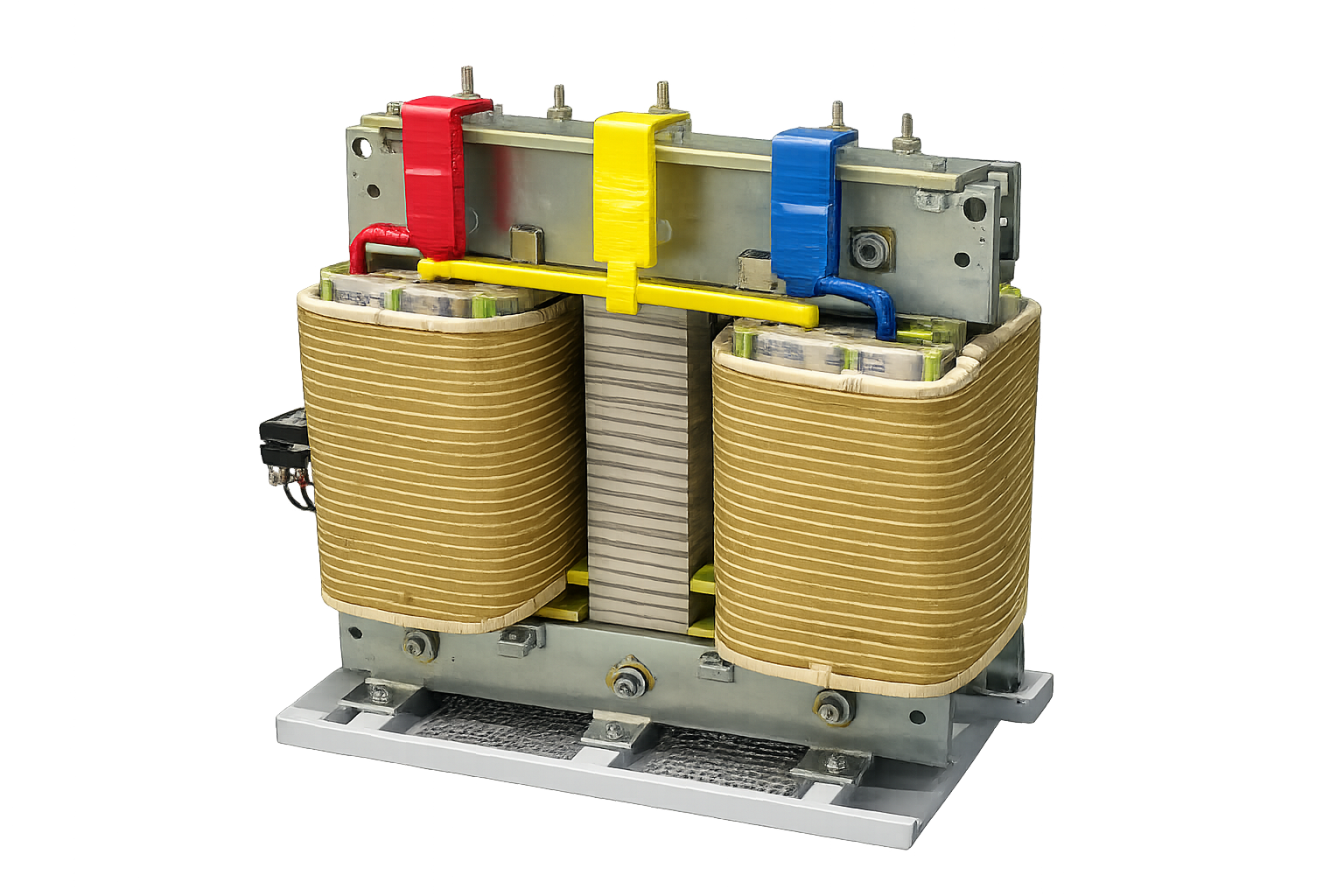
11kV Scott Connected Transformer

11kV Scott-Connected Transformers

Specialized 3-phase to 2-phase energy-converting transformers engineered for electric traction networks, heavy single-phase industrial furnaces, and unbalanced load balancing across 11kV networks.

Phase Conversion: 3-Phase 11kV to 2-Phase Output
Design Feature: Main & Teaser Winding Balance
Contact Us
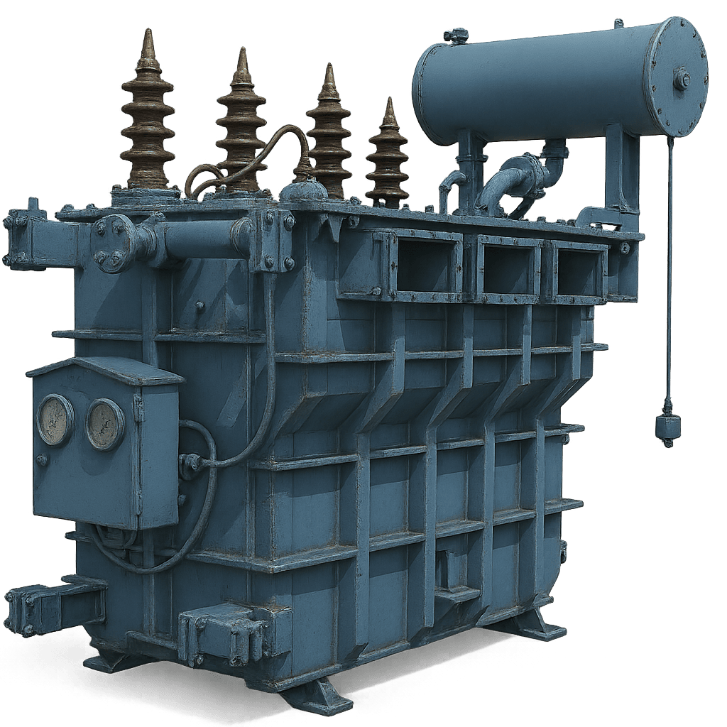
11kV Metallurgical Furnace Transformer

11kV Metallurgical Furnace Transformers

Engineered for extreme duty cycles in arc furnace and induction furnace applications. Provides ultra-high secondary current output with heavy internal mechanical bracing to withstand severe electromagnetic forces.

Duty Rating: Heavy Industrial Arc/Induction
Tap Changing: On-Load Tap Changer (OLTC) / OFTC
Contact Us
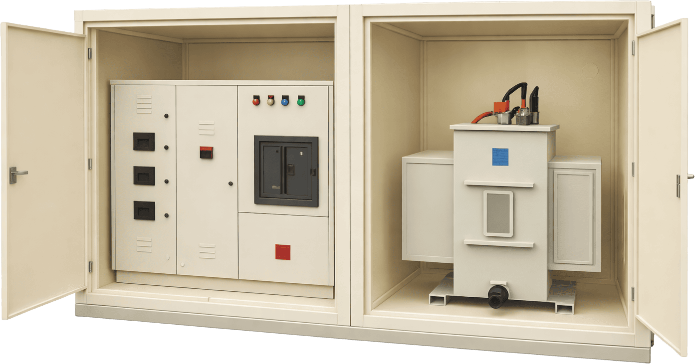
11kV Compact Substation CSS Sahara Transformers

11kV Integrated Compact Substations (CSS)

Factory-assembled, self-contained package substations housing an 11kV Vacuum Circuit Breaker (VCB) or Ring Main Unit (RMU), energy-efficient step-down transformer, and low-voltage distribution panel inside an IP54 enclosure.

Standard Rating: 100 kVA to 2000 kVA, 11kV
Enclosure: Drop-in Weatherproof Metal-Clad Enclosure
Contact Us

Future Procurement Trends for 11kV Power & Distribution Assets

The global power transmission and distribution (T&D) equipment procurement landscape is undergoing a structural shift driven by international carbon border mechanisms, grid digitalization, and renewable energy acceleration. Procurement managers specifying 11kV transformers must account for the following emerging trends over the next decade:

1. Transition to Biodegradable Ester Dielectric Fluids

Traditional mineral insulating oil is increasingly being replaced by synthetic and natural ester fluids (e.g., FR3). Ester fluids offer high fire flash points (>300°C vs. 140°C for mineral oil) and 100% biodegradability within 28 days. In 11kV application environments near waterways or crowded urban centers, ester-filled transformers prevent environmental contamination and eliminate costly fire deluge infrastructure.

2. Integration of Smart Grid & IoT Online Monitoring

Modern 11kV energy-efficient transformers are changing from passive electrical assets into intelligent nodes. B2B buyers now mandate built-in IoT sensors for continuous Dissolved Gas Analysis (DGA), real-time winding thermal imaging, optical fiber hotspot monitoring, and automated moisture tracking. This enables predictive maintenance, drastically extending transformer operational life.

3. Carbon Border Adjustment Mechanism (CBAM) Compliance

With environmental, social, and governance (ESG) compliance affecting global supply chains, international buyers scrutinize embodied carbon in steel, copper, and tank manufacturing. Choosing verified low-loss 11kV transformers built in ISO 14001 certified plants allows industrial enterprises to satisfy Scope 2 and Scope 3 carbon reduction quotas.

4. Hybrid Amorphous Core Technology

While CRGO steel remains dominant for large power units, distribution grids are adopting ultra-thin (25-micron) ribbon amorphous core alloys. Amorphous core 11kV transformers exhibit up to 70% lower no-load losses compared to standard CRGO silicon steel, making them the preferred technology for utility grids experiencing long periods of light load or standby operation.

Frequently Asked Technical & Procurement Questions

Expert answers to the most frequent technical, commercial, and quality assurance questions asked by international buyers when sourcing 11kV Energy Efficient Transformers.

What is the exact technical difference between IS 1180 Level 1, Level 2, and Level 3 energy efficiency ratings?

IS 1180 (Part 1): 2014 dictates the maximum total permissible losses (at 50% load and 100% load) for distribution transformers up to 33kV class in India. Level 1 is the baseline efficiency standard mandated by building codes. Level 2 demands lower loss thresholds, reducing total energy dissipation by approximately 5% to 8%. Level 3 is the premium efficiency tier, requiring ultra-low core and copper loss performance. Level 3 transformers utilize superior magnetic core grades (such as laser-scribed CRGO or Amorphous ribbon) and larger copper conductor cross-sections, resulting in maximum energy savings and the lowest total cost of ownership over a 25-year lifecycle.

Why is the 50% load loss parameter critical when sizing an 11kV industrial distribution transformer?

Most industrial, commercial, and utility distribution transformers rarely operate continuously at 100% nameplate capacity. Industry statistics indicate average real-world loading factors range between 40% and 65%. Because load losses scale quadratically ($P \propto I^2$), evaluating the loss profile at 50% load gives procurement officers an accurate representation of everyday operational power loss. A transformer optimized for low 50% load losses delivers higher overall weighted energy savings over its lifetime.

How does copper winding compare to aluminum winding in 11kV energy-efficient transformers?

While EC-grade aluminum conductors offer a lower initial CAPEX, high-purity electrolytic Copper (99.99% conductivity) provides superior electrical conductivity, higher thermal capacity, and smaller physical transformer footprint. Copper windings exhibit significantly lower electrical resistance ($I^2R$ loss), superior mechanical yield strength against electromagnetic short-circuit stresses, and lower expansion coefficients under cyclic overloading. For critical industrial facilities and continuous-duty power plants, copper-wound 11kV transformers deliver superior long-term reliability and lower overall lifetime losses.

What routine and type tests should global buyers require prior to factory acceptance (FAT)?

International procurement specs should mandate complete testing in accordance with IEC 60076 or IS 2026 standards. Routine Tests (100% of units): Measurement of winding resistance, voltage ratio, phase displacement (Vector Group verification), short-circuit impedance, load loss, no-load loss, insulation resistance (IR), separate-source AC withstand voltage, and induced overvoltage withstand. Type & Special Tests (Sample bases): Full Wave Lightning Impulse Withstand Test (BIL), Temperature Rise Test, Short-Circuit Dynamic Withstand Test (conducted at accredited labs such as CPRI/ERDA), Acoustic Sound Level Measurement, and Dissolved Gas Analysis (DGA).

Can an 11kV energy-efficient transformer operate safely under high harmonic conditions (e.g., VFDs, Inverters)?

Standard distribution transformers experience severe eddy current overheating and premature insulation degradation when subjected to non-linear harmonic currents generated by Variable Frequency Drives (VFDs), rectifiers, and solar inverters. For non-linear loads, buyers should specify K-Factor rated transformers (K-4, K-13, K-20) or Solar Inverter Duty Transformers. These units feature electrostatic shielding between primary and secondary windings, oversized neutral conductors (200% rating), transposed winding strip geometries, and specialized core flux density margins to handle harmonic distortion without derating.

What vector group is standard for 11kV to 433V step-down distribution transformers?

The global standard vector group for 11kV step-down distribution transformers feeding 3-phase, 4-wire low voltage systems is Dyn11. "D" indicates a Delta-connected 11kV primary winding; "y" signifies a Star (Wye) connected secondary winding (433V/415V); "n" represents an accessible neutral terminal; and "11" denotes a 30-degree phase lead of the low voltage phase relative to the high voltage phase. Dyn11 isolates supply-side zero-sequence third harmonics and provides a stable neutral point for unbalanced single-phase loads.

What are the recommended temperature rise limits for oil-immersed 11kV transformers?

Standard temperature rise limits above maximum ambient temperature (typically 45°C or 50°C) per IS 2026 / IEC 60076 are: Top Oil Temperature Rise: 50°C or 55°C (measured by top oil thermometer); Winding Temperature Rise: 55°C or 60°C (measured by resistance method). For severe high-ambient tropical environments (e.g., Middle East or desert mining operations), custom lower temperature rises (e.g., 40°C oil / 45°C winding) can be specified to ensure long insulation paper lifetime (Arrhenius rate equation compliance).

How does a dry-type cast resin transformer compare to an oil-filled transformer for 11kV applications?

Oil-filled 11kV transformers offer higher thermal dissipation capability, lower initial cost, and simpler outdoor maintenance. However, they require oil catchment pits, fire containment walls, and nitrogen fire suppression systems. Dry-Type Cast Resin Transformers (CRT) use epoxy resin encapsulated windings, making them completely flame-retardant, self-extinguishing, and moisture-proof. Dry-type units are mandatory for indoor commercial substations, hospital basements, data centers, and underground mining shafts where oil spill hazards or fire safety regulations prohibit liquid dielectric mediums.

What impact does core material selection (CRGO vs. Amorphous) have on physical transformer dimensions?

Amorphous metal alloys feature lower saturation flux density (~1.56 Tesla) compared to premium CRGO silicon steel (~1.9 Tesla). Consequently, an 11kV amorphous core transformer requires a larger magnetic core cross-sectional area, making the overall physical footprint and weight roughly 15% to 25% larger than an equivalent kVA-rated CRGO unit. Procurement teams must account for space restrictions inside existing substation rooms when replacing old CRGO units with amorphous core models.

What is the standard warranty and expected operational lifespan of a Sahara 11kV Transformer?

Sahara Transformers builds all 11kV units for an intended operational design life exceeding 25 to 30 years under rated loading conditions. Standard commercial warranties cover 18 months from the date of dispatch or 12 months from the date of commissioning, whichever occurs earlier. Extended warranty programs (up to 60 months) with integrated Annual Maintenance Contracts (AMC) and online condition monitoring packages are available upon request for international projects.

Have an active tender or technical spec requirement not listed here?

Contact Us

Why Global EPCs & Industrial Utilities Partner with Sahara Transformers

Established in 2007 in Pune, India, Sahara Transformers has engineered and delivered over 15,000 industrial transformers across 5 continents. Our engineering heritage is grounded in rigorous technical compliance, zero-compromise raw material sourcing, and certified quality control systems.

17+ Years of Engineering Mastership

Founded in 2007, our team of senior transformer design engineers brings deep domain expertise in electromagnetic design, structural thermal modeling, and short-circuit dynamics.

ISO-Certified Quality Infrastructure

Our modern manufacturing campus in Pune, Maharashtra operates under stringent ISO 9001:2015, ISO 14001:2015, and ISO 45001:2018 integrated management frameworks.

NABL & Accredited Laboratory Testing

Every 11kV transformer undergoes rigorous factory routine testing using calibrated digital instrumentation. Type-tested designs are validated by independent laboratories including CPRI and ERDA.

Prime Raw Material Guarantee

We source only prime-grade laser-scribed CRGO silicon steel from leading international mills and 99.99% pure electrolytic grade copper. No re-rolled steel or recycled insulation materials are ever permitted.

Bespoke Custom Engineering Capability

From special dual-voltage ratings to low-ambient Arctic or high-temperature desert modifications, our R&D engineering team designs tailor-made solutions for exact customer project specs.

Global Logistics & Export Field Support

Export-ready seaworthy vacuum packaging, full customs compliance support, and on-site field support for commissioning and maintenance anywhere in the world.

Optimize Your 11kV Distribution Network Efficiency Today

Connect directly with our engineering sales specialists in Pune for customized technical specifications, budgetary proposals, capitalized TCO calculations, or immediate factory quotes.

Contact Us