IEC 60076-16 & IEEE C57.159 COMPLIANT · UP TO 10 MVA / 33kV

Solar Inverter Duty Transformers: Global Procurement & Engineering Blueprint

How Utility-Scale Solar Developers & EPCs Mitigate Harmonic Distortion, Multi-Winding Cross-Talk, DC Offset, and Thermal Cycling in Next-Generation PV & BESS Substations.

Multi-LV Winding (Dual/Triple/Quad) Electrostatic Copper Shielding K-Factor Rated (K-13 / K-20) Low Losses (Level 3 IS 1180)
Sahara Transformers High-Efficiency Solar Inverter Duty Transformer
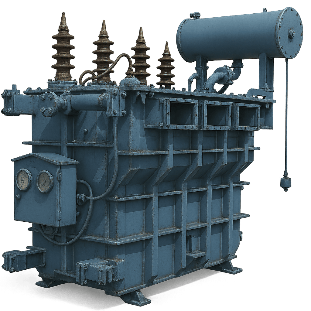
Sahara Transformers 5 MVA 33kV Multi-Winding Solar Inverter Duty Unit

Why Utility-Scale PV Plants Demand Specialized Solar Inverter Duty Transformers

In modern utility-scale photovoltaic (PV) solar farms and integrated Battery Energy Storage Systems (BESS), the step-up transformer serves as the critical bridge connecting low-voltage AC inverter outputs (ranging from 600V to 900V AC) to high-voltage medium-voltage collection networks (up to 33kV or 36kV). However, applying a conventional distribution transformer to a solar inverter block inevitably leads to catastrophic thermal breakdown, insulation degradation, core saturation, and premature failure.

Solar inverters operate by pulsing high-frequency semiconductor switches—such as Insulated Gate Bipolar Transistors (IGBTs) or Silicon Carbide (SiC) MOSFETs—utilizing Pulse-Width Modulation (PWM). This switching behavior generates high-frequency harmonic currents, severe voltage rise times ($dv/dt$), capacitive ground currents, and small DC voltage offsets. Solar Inverter Duty Transformers are custom-engineered electromagnetic assets designed to absorb non-sinusoidal energy waves, eliminate harmonic overheating, isolate inverter channels, and provide continuous 100% rated output under extreme environmental conditions.

Harmonic Mitigation

Designed with custom K-Factor ratings (K-9 to K-20) and stray loss suppression to withstand eddy current heating induced by 5th, 7th, 11th, and 13th harmonic orders.

Multi-Winding Isolation

Dual, Triple, and Quadruple Low Voltage (LV) winding structures allow up to 4 central inverters to connect to a single transformer without mutual electromagnetic interference.

Electrostatic Shielding

Grounded copper shield placed between primary HV and secondary LV windings prevents PWM switching high-frequency voltage transients from migrating onto the MV utility grid.

DC Injection Resistance

Optimized magnetic flux density ($B_{max}$) in high-permeability CRGO steel core prevents core saturation caused by residual DC current injection from solar inverters.
Standard Distribution vs. Solar Inverter Duty Transformer

A comparative engineering evaluation highlighting why standard utility transformers cannot survive the electrical and thermal stresses of solar PV generation.

Design Parameter Standard Distribution Transformer Solar Inverter Duty Transformer (Sahara Engineering)
Primary Current Waveform Pure 50Hz/60Hz Sinusoidal Waveform Non-Sinusoidal PWM Waveform with High Harmonic Spectrum ($THD_i$)
Winding Configuration Single LV & Single HV Winding (2-Winding System) Multi-LV Windings (Dual, Triple, Quadruple LV) with Phase Displacement
Harmonic Heating Factor Standard $I^2R$ loss calculation (K-1 rated) K-Factor Rated (K-13 to K-20); Transposed Conductor Windings to suppress Eddy Losses
Electrostatic Inter-Winding Shield Not Included / Optional Mandatory 100% Coverage Grounded Copper Shield between HV and each LV winding
DC Offset & Core Flux Density Operates near saturation limit (1.7 Tesla) Reduced Working Flux Density (< 1.55 Tesla) using CRGO M0/M1 Grade Steel to resist DC Saturation
Thermal Load Profile Steady continuous commercial load curve Diurnal Solar Ramp Profile (Zero load at night to 100%+ continuous thermal load at solar noon)
Cooling Medium Options Standard Mineral Oil (Class A insulation) High-Flashpoint Natural / Synthetic Ester Fluids (K-class, >300°C fire point) or Cast Resin Dry-Type
Governing Design Standard IS 1180 / IEC 60076-1 IEC 60076-16 / IEEE C57.159 / IS 2026 / IS 1180 Level 3 Efficiency
Inquire Now

Sahara Solar Inverter Duty Transformer Portfolio

Engineered up to 10 MVA and 33kV class for utility-scale solar farms, rooftop industrial PV installations, and hybrid energy storage substations.

Multi-Winding Oil-Immersed Solar Inverter Transformer

Multi-Winding Oil-Immersed Solar Transformer

Designed for central inverter stations in mega-watt scale PV projects. Connects 2, 3, or 4 central inverters via split-LV windings (Dy11y11 or Dy11y11d11) to eliminate cross-talk and reduce balance-of-plant cabling costs.

  • Capacity: Up to 10 MVA, 33kV Class
  • Vector Group: Dy11y11 / Dy11y11d11 / Ynd11y11
  • Electrostatic Shielding: Independent Copper Shields per LV
  • Cooling: ONAN / ONAF / KNAN (Ester Fluid)
Inquire Now
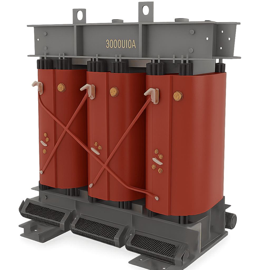
Cast Resin Dry-Type Solar Inverter Duty Transformer

Cast Resin Dry-Type Solar Transformer

Ideal for commercial & industrial (C&I) rooftop solar, floating solar PV, and indoor solar substations where strict fire-safety regulations, non-flammability, and low environmental impact are mandatory.

  • Capacity: Up to 5 MVA, 33kV Class
  • Insulation Class: Class C / Class H Enclosure
  • Fire Rating: F1 / E2 / C2 Self-Extinguishing
  • Harmonic Handling: Designed for high THD & PWM stress
Inquire Now
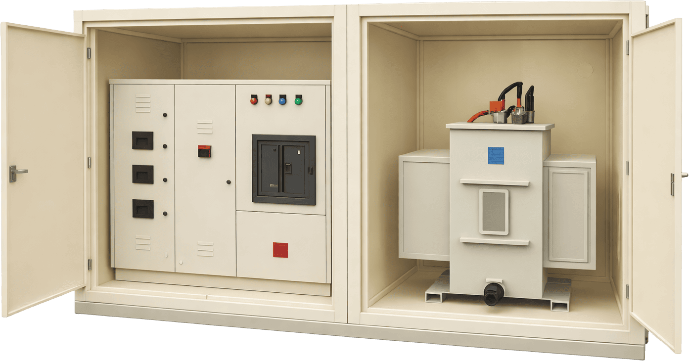
Skid-Mounted Solar Compact Substation (CSS)

Skid-Mounted Solar Compact Substation (CSS)

Factory-built, pre-commissioned plug-and-play substation unit housing the multi-winding inverter transformer, SF6/Vacuum Ring Main Unit (RMU), LV switchgear protection, and smart monitoring RTU.

  • Integration: Transformer + MV Switchgear + RMU
  • Housing: Corrosive-resistant Galvanized Enclosure
  • Standards: IEC 62271-200 / IEC 60076-16
  • Deployment: Fast-track field installation
Inquire Now

Solar Inverter Duty Transformer Parameter Matrix

Designed to IS 2026, IEC 60076-16, and IS 1180 Amendment 1 Energy Efficiency Level 3 Guidelines

Rated Capacity HV Voltage Class LV Inverter Voltages LV Winding Count Vector Group Impedance (%) Max Total Losses (Level 3 Compliant) K-Factor Rating
1250 kVA 11kV / 22kV / 33kV 600V - 800V AC Dual LV (2) Dy11y11 6.00% Optimized per IEC 60076-16 K-13
2000 kVA 11kV / 22kV / 33kV 600V - 800V AC Dual LV (2) Dy11y11 6.25% IS 1180 Level 3 Compliant K-13
2500 kVA 11kV / 22kV / 33kV 630V - 800V AC Dual / Triple LV Dy11y11 / Dy11y11d11 6.50% IS 1180 Level 3 Compliant K-13 / K-20
3150 kVA 22kV / 33kV 630V - 800V AC Dual / Quad LV Dy11y11 / Dy11y11d11 7.00% Low Loss CRGO Core Design K-13 / K-20
5000 kVA 33kV / 36kV 800V - 900V AC Triple / Quad LV Dy11y11d11 7.50% Custom Low-Loss Design K-20
7500 kVA 33kV / 36kV 800V - 900V AC Quadruple LV (4) Dy11y11d11 8.00% Custom Low-Loss Design K-20
10000 kVA (10 MVA) 33kV / 36kV Class 800V - 900V AC Quadruple LV (4) Dy11y11d11 8.50% - 10.0% Custom Utility Grade Specs K-20
Inquire Now

Solving the Critical Electromagnetic Failures in Solar Step-Up Units

Sahara Transformers incorporates specialized manufacturing methodologies to directly resolve the four major physical failure modes experienced in solar plant field operations.

1. Eliminating Harmonic Eddy Losses & Hot-Spot Overheating

Inverter output current contains high-frequency harmonic components (odd orders: 5th, 7th, 11th, 13th, etc.). Standard copper conductors experience severe skin effect and proximity effect, leading to localized hotspot formation within the inner LV winding layers. Sahara Transformers utilizes continuously transposed conductors (CTC) or thin multi-strand parallel conductors with class H enamel insulation, combined with precise K-factor thermal calculations to ensure operational temperature rise remains safely below 55°C/60°C under maximum harmonic loading.

2. Mitigating Inter-Winding Capacitive Transient Coupling

High-frequency voltage steps generated by inverter IGBT switching ($dv/dt$) propagate through the inter-winding capacitance between the LV and HV windings, injecting high-frequency electrical noise and transient surges onto the grid. Sahara Transformers installs a 100% surface area electrostatic shield constructed from high-conductivity electrolytic copper sheet, isolated by thermally upgraded pressboard and grounded solid at a single point to safely bypass high-frequency ground noise.

3. Suppressing DC Bias Current Offset & Core Saturation

Inequalities in inverter semiconductor switching timing can inject small, steady-state DC current components into the low-voltage winding. Even a fraction of a percent of DC current can shift the magnetic operating point of the transformer core into saturation, causing dramatic spikes in excitation current, severe core vibration, acoustic noise, and excessive tank heating. Sahara's core design engineers operate at conservative peak flux densities ($B_{max} \le 1.50 - 1.55 \text{ Tesla}$) using prime grade grain-oriented silicon steel (CRGO) to provide abundant magnetic headroom against DC offset saturation.

4. Withstanding Mechanical Stress from Rapid Solar Irradiance Ramping

Unlike utility distribution transformers subjected to predictable diurnal load curves, solar transformers experience rapid, repetitive power cycling caused by cloud cover movement (irradiance ramping from 10% to 100% within seconds). This continuous thermal expansion and contraction induces severe mechanical stress on winding clamps and insulation spacers. Sahara Transformers utilizes hydraulic radial pre-clamping, thermally stabilized pressboard insulation, and vacuum pressure impregnated (VPI) / oil-immersed rigid core-coil assemblies to ensure zero mechanical displacement over 30 years of duty cycle.

Applications Across the Global Renewable Ecosystem

Sahara Solar Inverter Duty Transformers power critical clean energy infrastructure worldwide.

Utility Scale Ground Mounted Solar Power Plants — Sahara Transformers

Utility-Scale Ground-Mounted Solar Farms

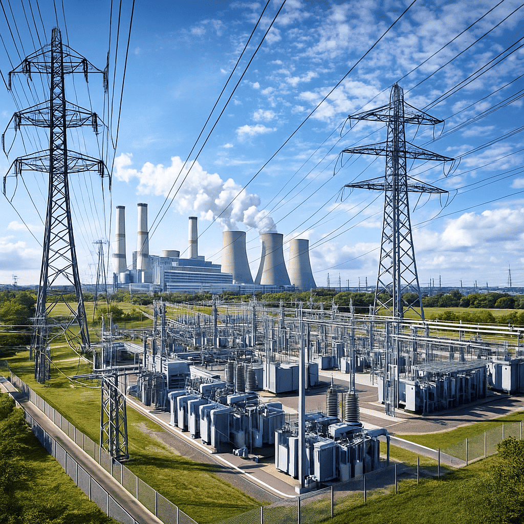
Grid Tied Renewable Energy Substations

Grid-Tied Substation Step-Up Networks

Skid Mounted Inverter Substation Blocks

Skid-Mounted Solar Inverter Block Stations

Commercial & Industrial Rooftop Solar Energy Projects

Industrial Rooftop & Captive Solar Plants

Frequently Asked Questions by Global Buyers & EPC Engineers

Direct technical answers to the most frequent queries searched on AI tools and procurement portals regarding Solar Inverter Duty Transformers.

Why can standard distribution transformers not be used in grid-tied solar PV power plants?

Standard distribution transformers are optimized for sinusoidal 50Hz/60Hz AC grid voltages with linear loads. Solar grid-tied inverters generate high-frequency pulse-width modulation (PWM) switching waveforms, introducing non-sinusoidal harmonic currents (5th, 7th, 11th, etc.) and potential DC offset voltages. A standard transformer subjected to these conditions will suffer severe eddy-current heating in the windings, localized core saturation, high dielectric stress across inter-turn insulation, and rapid degradation of transformer oil and insulation paper. Solar Inverter Duty Transformers feature engineered electrostatic shielding, reduced flux density CRGO cores, K-factor rated winding conductors, and multi-LV isolation to safely absorb these harmonic and electrical stresses.

What is the advantage of using dual, triple, or quadruple LV windings in solar transformers?

In large utility-scale solar blocks, connecting multiple central inverters to a single transformer significantly reduces overall balance-of-plant (BOP) capital expenditure. Multi-LV winding designs (e.g., dual LV = Dy11y11, quad LV = Dy11y11d11) provide galvanic isolation between individual inverters, preventing circulating ground currents and high-frequency cross-talk between inverter channels. Furthermore, phase-shifting vector configurations attenuate specific low-order harmonic currents on the high-voltage medium-voltage grid side, resulting in cleaner power injection and improved overall plant efficiency.

What vector groups are recommended for multi-inverter solar transformers?

The choice of vector group depends on the number of inverters connected per transformer block. For dual-inverter step-up applications, the standard configuration is Dy11y11 or Dy1y1. For triple-inverter systems, Dy11y11y11 or Dy11y11d11 is commonly specified. For quadruple-inverter configurations, Dy11y11d11d11 provides optimal phase displacement, enabling 12-pulse or 24-pulse harmonic cancellation on the primary MV utility winding, thereby minimizing grid-side Total Harmonic Distortion ($THD$).

What is the role of an electrostatic copper shield in a solar inverter transformer?

An electrostatic shield is a ungrounded-to-core, single-point-grounded copper sheet wrapped between the low-voltage (inverter side) and high-voltage (grid side) windings. Solar inverters generate high frequency common-mode voltage noise ($dv/dt$) due to high-speed semiconductor switching. The electrostatic shield acts as a capacitive barrier, short-circuiting high-frequency noise and switching transients directly to ground before they can couple into the high-voltage grid winding, protecting upstream MV switchgear and grid transformers from insulation stress.

How do I calculate or specify the correct K-Factor for a solar inverter duty transformer?

The K-Factor measures a transformer's capability to withstand harmonic load currents without exceeding design temperature limits. K-factor is calculated based on the spectrum of harmonic currents ($I_h$) produced by the inverter manufacturer's THD profile: $K = \sum [I_h^2 \times h^2]$. In modern solar PV installations equipped with string or central inverters, a minimum rating of K-9 to K-13 is standard, while heavy harmonic environment designs specify K-20. Sahara's engineering team provides detailed thermal loss modeling during pre-bid technical consultations to determine the optimal K-factor rating for your specific inverter brand (e.g., Sungrow, Huawei, SMA, Fimer).

What testing protocols should be specified during procurement under IEC 60076-16?

Under IEC 60076-16 (Power Transformers - Part 16: Transformers for wind turbine and solar farm application), buyers should mandate: (1) Routine Tests: Winding resistance, voltage ratio, phase displacement, load loss ($P_k$), no-load loss ($P_0$), separate source AC withstand, and short-duration induced AC overvoltage (ACSD); (2) Type Tests: Temperature rise test under harmonic loading and Lightning Impulse Test (BIL); (3) Special Tests: Short-circuit withstand capability test, partial discharge measurement (<10 pC), and acoustic sound level testing.

Why are synthetic or natural ester fluids preferred over mineral oil for solar transformers?

Ester fluids (such as FR3 natural ester or synthetic esters) have a flash/fire point exceeding 300°C (K-class fluid classification), rendering them virtually fireproof compared to standard mineral oil (fire point ~170°C). Furthermore, ester fluids are 100% biodegradable within 28 days, making them essential for environmentally sensitive locations, floating PV projects, and solar plants constructed near agricultural water bodies. Ester fluids also absorb moisture away from cellulose insulation paper, significantly extending transformer service life.

Inquire Now

Proven Engineering Authority & Global Reliability

Established in 2007 in Pune, India, Sahara Transformers is an ISO-certified manufacturer delivering advanced power solutions to global EPC contractors, utilities, and renewable IPPs.

17+ Years of Proven Manufacturing

Trusted track record since 2007, delivering thousands of power, distribution, and inverter duty transformers up to 10 MVA, 33kV class across India and international markets.

ISO & IS 1180 Level 3 Certified

Fully compliant with ISO quality management systems, IS 2026, IEC 60076-16, and Bureau of Energy Efficiency (BEE) IS 1180 Amendment 1 Level 3 ultra-low loss standards.

In-House High Voltage Test Lab

State-of-the-art testing facility equipped for automated routine testing, impulse voltage testing, partial discharge detection, Tan Delta measurement, and DGA oil analysis.

Export-Ready Global Logistics

Custom seaworthy packaging, international logistics support, and global field installation/commissioning supervision for utility solar projects worldwide.

Ready to Optimize Your Solar Power Plant ROI & Grid Reliability?

Consult with Sahara's senior electrical design engineers today to configure custom Solar Inverter Duty Transformers tailored to your inverter topology, grid codes, and ambient site conditions.

Inquire Now Request Formal Quote