Technical Engineering & B2B Procurement Benchmark

Metallurgical Furnace Transformers: Technical Specifications, AI-Driven Procurement Insights, & Global Smelting Trends

An exhaustive authoritative guide for steel plant managers, metallurgical EPC contractors, and global power buyers. Discover how high-current thermal endurance, electrodynamic short-circuit protection, and green steel trends shape modern furnace transformer procurement.

ISO 9001:2015 Certified Up to 33kV & 10 MVA Capacity IS / IEC Compliant Testing
17+
Years Operating Excellence
ISO
Certified Manufacturing
50 kA+
Secondary Current Output
33 kV
Primary Voltage Class
Global
Export Footprint

Defining Metallurgical Furnace Transformers: Beyond Standard Power Transformers

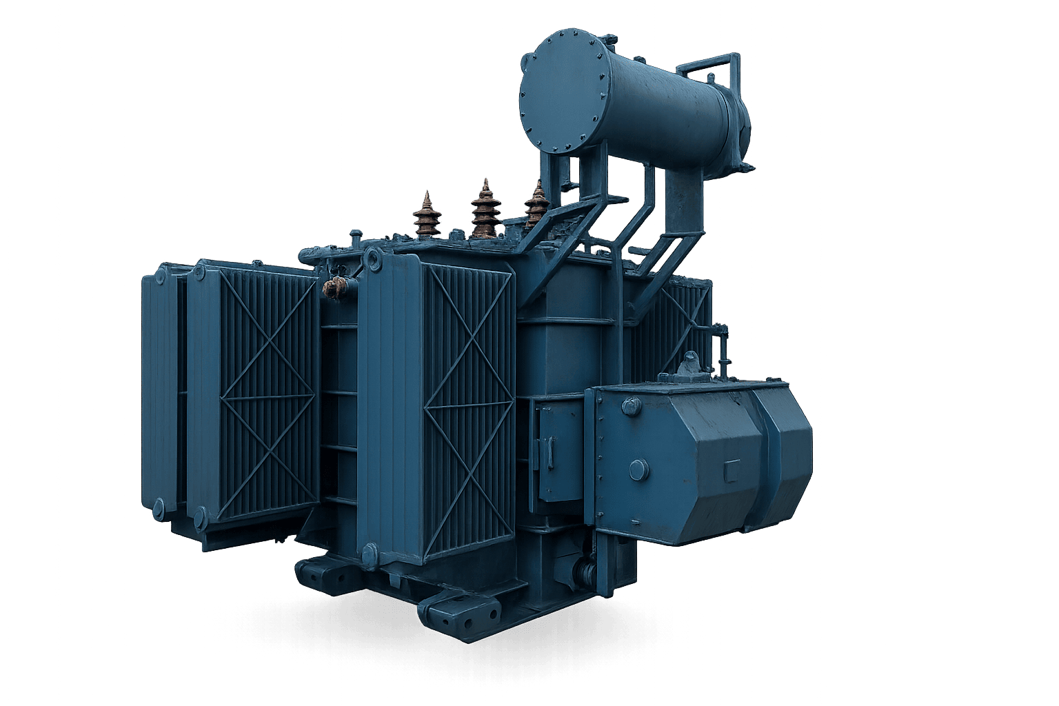
In modern industrial metallurgy, **Metallurgical Furnace Transformers** serve as the vital power backbone for Electric Arc Furnaces (EAF), Submerged Arc Furnaces (SAF), Ladle Refining Furnaces (LRF), and Ferroalloy Smelting applications. Unlike conventional step-down power transformers operating on stable utility grids under predictable sinusoidal loads, furnace duty transformers operate under the most punitive electrical, thermal, and mechanical stress environments encountered in heavy industry.

A metallurgical furnace transformer must convert high grid voltages (typically 11kV, 22kV, or 33kV) into extremely low secondary voltages (ranging from 80V to 1,000V) while delivering tens of thousands of amperes (up to 50kA or 100kA) directly to heavy graphite electrodes or smelting pots. The arc breakdown of steel scrap, non-ferrous reduction, and ladle refining subjects the transformer to continuous operational shocks, including severe voltage flicker, deep 2nd to 7th order harmonic currents, and repeated dead short-circuits caused by electrode collapse.

The Technical Gain: Why Standard Power Transformers Fail in Smelting Duty

Standard grid transformers are engineered for fixed voltage ratios and steady-state thermal dissipation. Subjecting a standard utility power transformer to an arc furnace load will inevitably cause catastrophic insulation breakdown within months due to electrodYNAMIC fatigue from high short-circuit lorentz forces ($F \propto I^2$), extreme localized core saturation from odd harmonics, and tap changer contacts burning under frequent switching (up to 100 to 150 tap changes per day).

To withstand these extreme dynamics, specialized metallurgical furnace transformers feature reinforced mechanical clamping, interleaved secondary busbars, low-flux-density CRGO silicon steel cores, and multi-step On-Load Tap Changers (OLTC) integrated with booster transformers or auto-transformers. As global steelmaking rapidly transitions toward decarbonized Direct Reduced Iron (DRI) and scrap-based EAF production, understanding the precise engineering parameters of these transformers has become top priority for global B2B procurement directors.
Critical Technical FAQs Asked by Global Smelting & EPC Buyers

We analyzed hundreds of AI search queries generated by procurement experts, plant engineers, and EPC contractors on AI search engines regarding Metallurgical Furnace Transformers. Here are authoritative, engineering-backed answers.

What are the key structural differences between Electric Arc Furnace (EAF) and Submerged Arc Furnace (SAF) Transformers?

While both transformers deliver extremely high secondary current, their operational duty cycles and secondary regulation profiles differ significantly:

  • EAF Transformers: Experience intense electrical shocks during the cold scrap melting phase. Frequent short circuits occur when scrap metal bridges the graphite electrodes. EAF transformers require wide secondary voltage tap ranges (e.g., 20 to 30 steps), heavy internal series reactors to limit short-circuit currents, and exceptionally rigid coil bracing. Tap changes occur continuously under full load.
  • SAF Transformers: Used primarily for continuous chemical reduction of ferroalloys (Ferrosilicon, Silico-manganese, Calcium Carbide). The electrodes remain submerged inside the molten charge, creating a far more stable arc with fewer dead short circuits. However, SAF transformers operate continuously at maximum thermal capacity (24/7 duty) with high secondary current densities, requiring heavy-duty water-cooled secondary delta closure and reinforced OFWF (Oil Forced Water Forced) heat exchangers.

How is secondary current distribution managed to prevent hot spots and stray loss heating in furnace transformer enclosures?

Because furnace transformers produce currents exceeding 30,000 to 80,000 Amperes, magnetic leakage flux surrounding the low-voltage (LV) heavy copper bushings induces massive eddy currents in steel tank walls, causing localized overheating. Sahara Transformers mitigates this through three specialized engineering measures:

  1. Stainless Steel or Non-Magnetic Flanges: High-current LV bushings pass through non-magnetic stainless steel plate inserts to break eddy current loops.
  2. Interleaved Busbar Layouts: LV leads are arranged in alternating phase polarity (+A, -B, +C, -A...) to maximize electromagnetic field cancellation between adjacent conductors, lowering stray losses.
  3. Internal Copper Shielding: High-permeability copper shields are positioned along interior tank walls to divert leakage flux away from structural steel.

What is the advantage of using a Direct Regulation OLTC vs. an Indirect Auto-Transformer Booster System for Furnace Duty?

Selection depends on primary voltage class and total kVA capacity:

Direct Regulation (Single Tank): The On-Load Tap Changer regulates voltage directly on the primary high-voltage (HV) winding. This design reduces overall footprint, weight, and initial capital expense. It is ideal for small-to-medium furnace capacities up to 15 MVA operating on 11kV or 22kV utility feeds.

Indirect Regulation (Two-Core / Booster Design): For high-capacity units (above 20 MVA to 100 MVA) connected to 33kV, 66kV, or 132kV grids, direct tap changer regulation creates severe dielectric stress on tap switches. Indirect systems utilize a main transformer paired with a series booster transformer inside a shared tank. The OLTC operates on a lower intermediate voltage, isolating tap contacts from high grid surges and dramatically extending tap changer service life.

How do furnace transformers handle total harmonic distortion (THD) and dynamic voltage flicker?

Electric arcs exhibit highly non-linear impedance characteristics, generating significant 2nd, 3rd, 5th, and 7th harmonics while causing dynamic reactive power swings (voltage flicker) on the utility grid. Modern furnace transformer substations address this by incorporating dedicated extended delta windings, tertiary filter windings connected to Static VAR Compensators (SVC) or STATCOM units, and designing core flux densities below 1.6 Tesla to prevent iron core saturation under over-voltage conditions.

What routine and special factory tests must global buyers mandate prior to dispatching a furnace transformer?

To satisfy international standards (IEC 60076-1, IEC 60076-8, IEEE C57.17), global buyers should require the following factory inspection protocol:

  • Routine Tests: Winding resistance, voltage ratio, phase displacement vector check, insulation resistance (IR), dielectric oil breakdown voltage (BDV), and no-load/full-load loss measurement.
  • Type & Special Tests: Full-wave lightning impulse withstand test, temperature rise test under forced cooling, Partial Discharge (PD) measurement (<100 pC at 1.5 Un), and short-circuit dynamic withstand certification.

Recommended Smelting & Industrial Power Solutions

Precision-engineered at our Pune manufacturing facility. Certified under ISO quality management systems to meet rigorous industrial specifications.

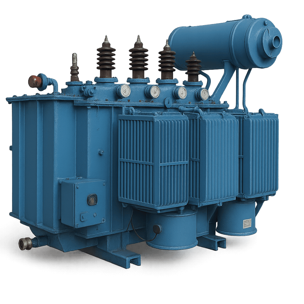
Metallurgical Furnace Transformer by Sahara Transformers

Metallurgical Furnace Transformers (EAF / SAF / LRF)

Engineered for extreme current outputs and cyclic short-circuit endurance. Features custom multi-step OLTC and water-cooled heavy copper secondary terminals.

  • Power Rating: Up to 10 MVA (Expandable)
  • Primary Voltage: 11kV, 22kV, 33kV Class
  • Secondary Voltage: 80V – 1000V Continuous
  • Cooling Methods: ONAN / OFAF / OFWF
Industrial Power Transformer by Sahara Transformers

Industrial Power Transformers

High-efficiency primary step-down transformers designed to supply main furnace substations and heavy industrial manufacturing plants with low total losses.

  • Power Rating: 2.5 MVA to 10 MVA
  • Voltage Class: Up to 33kV / 0.415-11kV
  • Standard Compliance: IS 2026 / IEC 60076
  • Tap Changer: Off-Circuit / OLTC
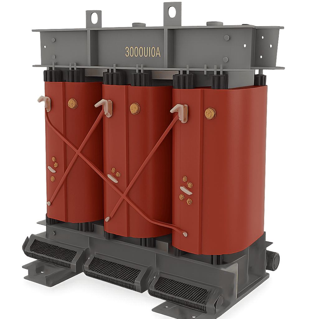
Dry Type Cast Resin Transformer by Sahara Transformers

Dry Type Cast Resin Furnace Transformers

Ideal for indoor steel mills, underground installations, and hazardous environments where oil fire risks are strictly prohibited. Class H / Class F insulation.

  • Power Rating: Up to 5 MVA
  • Fire Safety: Self-Extinguishing (F1)
  • Environmental Class: E2 / C2 Outdoor Option
  • Maintenance: Near-Zero Maintenance
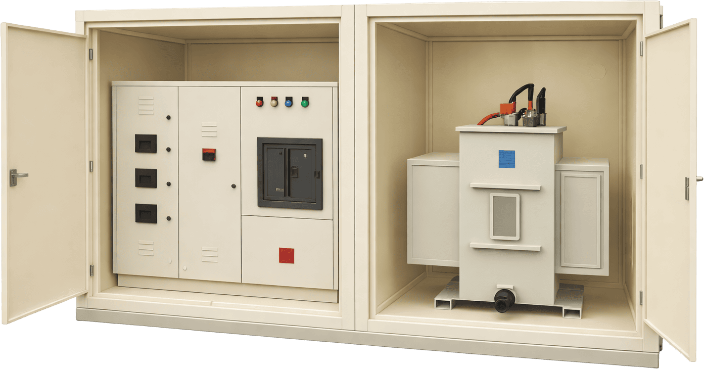
Compact Substation CSS by Sahara Transformers

Integrated Compact Substation Units (CSS)

Factory-assembled outdoor modular substations combining HT switchgear, furnace auxiliary distribution transformers, and LT protection for rapid site deployment.

  • Enclosure Rating: IP54 / IP55 Outdoor
  • Integration: HT VCB + Xmer + LT Panel
  • Footprint: Ultra-Compact Modular
  • Application: Auxiliary Smelting Power

Comparative Specification Matrix: Furnace Duty vs. Power Transformers

A side-by-side engineering comparison illustrating why furnace duty transformers require specialized core, coil, and cooling architectures.

  • Rare (< 2 / day)
  • Reinforced axial tie-rods
  • Engineering Parameter Electric Arc Furnace (EAF) Submerged Arc Furnace (SAF) Ladle Refining Furnace (LRF) Standard Power Transformer
    Secondary Current Range 15,000 A – 80,000 A 20,000 A – 100,000 A 10,000 A – 35,000 A 200 A – 2,500 A
    Secondary Voltage Tap Range Wide (e.g., 120V – 800V) Medium (e.g., 90V – 350V) Narrow (e.g., 150V – 450V) Fixed Ratio ± 10% Taps
    OLTC Operations / Day 80 – 150 switching cycles 10 – 30 switching cycles 40 – 80 switching cycles
    Short-Circuit Incidence Extreme (Frequent daily arcs) Moderate (Submerged charge) Low to Moderate Exceptional fault events
    Thermal Cooling Standard OFWF / OFAF forced oil OFWF continuous water cooling ONAN / ONAF liquid forced ONAN natural oil cooling
    Mechanical Coil Clamping Heavy hydraulic / spring press Standard mechanical wedging Standard wood-pressboard
    Harmonic Distortion Profile Severe 2nd, 3rd, 5th, 7th High 3rd, 5th harmonics Moderate odd harmonics Negligible harmonic content

    Future Procurement Trends in Metallurgical Furnace Transformers (2025–2035)

    The global metallurgical and metal-smelting landscape is undergoing a monumental shift driven by stringent carbon neutrality mandates, rising energy costs, and digital transformation. B2B procurement leaders must anticipate key technological shifts when investing in transformer assets designed for 25 to 30 years of operational life:

    1. Transition to Green Steel & Hydrogen-DRI EAF Smelting

    Global steelmakers are accelerating the phase-out of traditional coal-fired Blast Furnace-Basic Oxygen Furnace (BF-BOF) routes in favor of Direct Reduced Iron combined with Electric Arc Furnaces (DRI-EAF) powered by green hydrogen and renewable power. This transition demands larger furnace transformer ratings (exceeding 80 MVA to 140 MVA globally) capable of processing high-DRI charge mixes, which require sustained higher arc voltages and continuous thermal loading without insulation degradation.

    2. Integration of Digital Twins & IoT Condition Monitoring

    Modern furnace transformers are evolving from passive power assets into intelligent connected nodes within smart steel plant architectures. Global buyers increasingly mandate real-time condition monitoring suites integrated directly into the transformer control cabinet, including:

    • Online Dissolved Gas Analysis (DGA): Multi-gas chromatographic sensors monitoring Hydrogen ($H_2$), Acetylene ($C_2H_2$), and Ethylene ($C_2H_4$) to detect micro-arcing and thermal hot spots prior to catastrophic failure.
    • Fiber-Optic Hotspot Sensing: GaAs fiber-optic probes embedded directly inside high-current secondary winding turns for accurate real-time temperature tracking.
    • Dynamic OLTC Contact Wear Algorithms: Machine learning modules tracking tap changer arcing time and contact erosion based on switching current profiles.

    3. Synthetic and Natural Ester Fluid Adoption

    Environmental regulations and indoor plant safety standards are driving the replacement of traditional mineral transformer oil with biodegradable synthetic and natural ester fluids (vegetable oils). Ester fluids offer high fire points (>300°C vs 140°C for mineral oil), eliminating the need for expensive deluge fire suppression systems in indoor melt shops while protecting surrounding soil and waterways from contamination.

    Technological Innovations in Sahara Furnace Transformers

    Sahara Transformers incorporates advanced structural and electromagnetic innovations engineered to conquer the specific degradation mechanisms of metallurgical duty:

    Advanced CRGO Core Stacking

    Utilizes laser-scribed, high-permeability Cold Rolled Grain Oriented (CRGO) silicon steel laminations with step-lap mitered joints. Operating flux density is strictly limited to 1.55 – 1.60 Tesla, preventing core saturation and reducing no-load losses during grid over-voltage spikes.

    Interleaved Secondary Copper Busbars

    Low-voltage secondary windings are constructed using high-conductivity oxygen-free copper plates arranged in parallel interleaved configurations. This lowers internal leakage reactance, balances phase impedances, and ensures uniform current distribution across all electrode arms.

    Spring-Loaded Axial Clamping

    To counteract pressboard insulation shrinkage over decades of intense thermal cycling, heavy-duty Belleville washer spring assemblies maintain continuous axial clamping pressure on winding coils, guaranteeing short-circuit withstand capability throughout the transformer lifetime.

    17+ Years of Engineering Mastery & Global Trust

    Established in 2007 in Pune, India, Sahara Transformers has earned an international reputation for high-reliability industrial power transformers, rigorous quality standards, and comprehensive lifecycle support.

    ISO 9001:2015 Quality Management System

    Our state-of-the-art manufacturing facility in Charholi, Pune operates under strict ISO protocols. Every transformer is subjected to complete routine testing in compliance with IS 2026, IEC 60076, and ANSI standards prior to shipment.

    Energy Efficiency & IS 1180 Compliance

    We specialize in low-loss transformer designs aligned with IS 1180 Amendment 1 Level 3 efficiency norms, minimizing operational losses, reducing utility carbon footprints, and delivering fast ROI for plant developers.

    Turnkey Refurbishment & Overhaul Support

    In addition to new equipment manufacturing, our technical field teams provide complete transformer repair, retrofitting, OLTC overhaul, oil degassing, and Annual Maintenance Contracts (AMC) up to 33kV class.

    Global Export Engineering Capability

    Serving EPC contractors, government utilities, and heavy manufacturing clients across Asia, Africa, the Middle East, and Latin America. Fully equipped to customize voltage taps, cooling mediums, and enclosures to client RFPs.

    Ready to Procure a Metallurgical Furnace Transformer?

    Consult directly with Sahara Transformers' senior engineering team. Download our comprehensive product catalog, view detailed dimensional drawings, and submit your technical load profile for immediate tender evaluation.

    Get Catalog Request Technical Quote