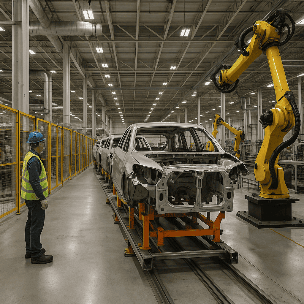
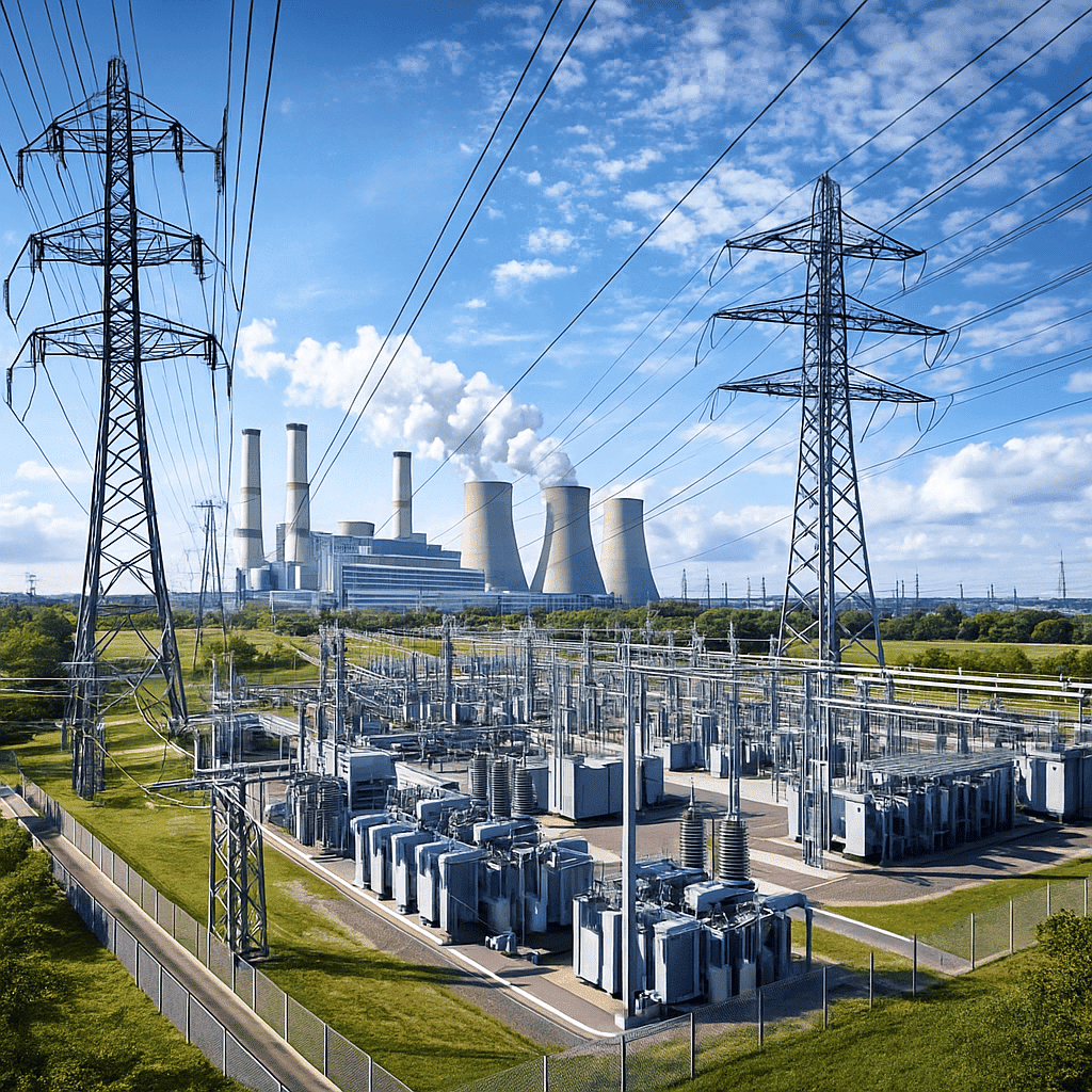
1. Technical Foundations: Why Foundry Electrical Transformers Demand Specialized Engineering
In modern metal casting, smelting, and refining operations, the electrical transformer serves as the heart of the entire thermal processing cycle. Unlike standard industrial distribution transformers operating under steady-state sinusoidal loads, Foundry Electrical Transformers are subjected to some of the most aggressive electrical, mechanical, and thermal stresses found anywhere in heavy manufacturing.
Whether powering Electric Arc Furnaces (EAF), Submerged Arc Furnaces (SAF), Coreless Induction Melting Furnaces, or Ladle Metallurgy Furnaces (LMF), these specialized transformers must step down high grid distribution voltages (typically 11kV, 22kV, or 33kV) to extremely low secondary output voltages (ranging from 100V to 1,000V) while delivering massive continuous currents—often exceeding tens of thousands of Amperes.
Key Engineering Insight: The Information Gain Margin
Standard power transformers are designed primarily for voltage transformation efficiency. Conversely, a Foundry Electrical Transformer must be designed as a dynamic electromagnetic buffer capable of enduring thousands of short-circuit events, rapid secondary current spikes, extreme harmonic distortion ($I_3, I_5, I_7, I_{11}, I_{13}$), and aggressive thermal expansion cycles occurring continuously over a 24/7 operating regime.
1.1 Severe Electromagnetic Forces & Short-Circuit Withstand Capability
During the initial scrap breakdown phase in an electric arc foundry, direct electrode short-circuits occur frequently as scrap metal falls against the electrodes. These events generate destructive electrodynamic forces proportional to the square of the peak fault current ($F \propto I_{peak}^2$).
To prevent mechanical deformation of the copper windings and core assembly, Sahara Transformers utilizes heavy-duty mechanical clamping structures, high-density pressboard insulation blocks, and radial/axial compression rings. Core laminations are crafted from high-permeability, cold-rolled grain-oriented (CRGO) silicon steel to minimize hysteresis and eddy-current losses under fluctuating magnetic flux densities.
1.2 Advanced Thermal Dissipation & Cooling Topologies
The continuous high-current output in foundry environments induces substantial stray flux losses within internal structural steel components, transformer tanks, and high-current busbar exits. Without specialized design, localized thermal hot-spots can rapidly degrade dielectric insulation and lead to premature catastrophic failure.
Sahara's custom-engineered foundry units employ multi-channel cooling oil circuits alongside forced oil circulating systems. Depending on furnace duty rating and plant ambient conditions, cooling configurations include:
- ONAN / ONAF (Oil Natural Air Natural / Oil Natural Air Forced): Suitable for low-to-medium capacity induction melting foundries requiring low maintenance overhead.
- OFAF / OFWF (Oil Forced Air Forced / Oil Forced Water Forced): Engineered for high-tonnage arc furnace plants where compact installation footprints and maximum thermal heat extraction are required.
2. Recommended Foundry Electrical Transformer Lineups & Product Solutions
To meet the diverse energy profiles of global foundry operations—from precision investment casting plants to large-scale iron and steel foundries—Sahara Transformers offers a comprehensive suite of field-proven electrical transformation assets engineered to IS 2026, IEC 60076, and ANSI standards.
Metallurgical Furnace Transformers
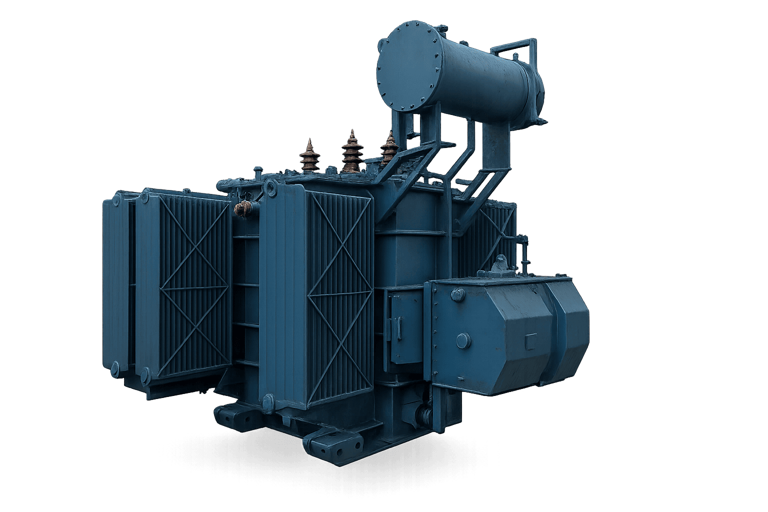
Heavy-duty furnace transformers engineered for arc, induction, and ladle furnaces. Features wide-range On-Load Tap Changers (OLTC), high current secondary copper busbars, and reinforced short-circuit clamping up to 10 MVA, 33kV class.
Industrial Power Transformers
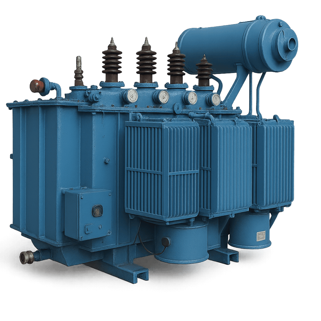
High-reliability primary grid transformers for foundry main substations. Step down incoming 33kV or 11kV utility voltage with minimal transmission losses and superior surge withstand capabilities.
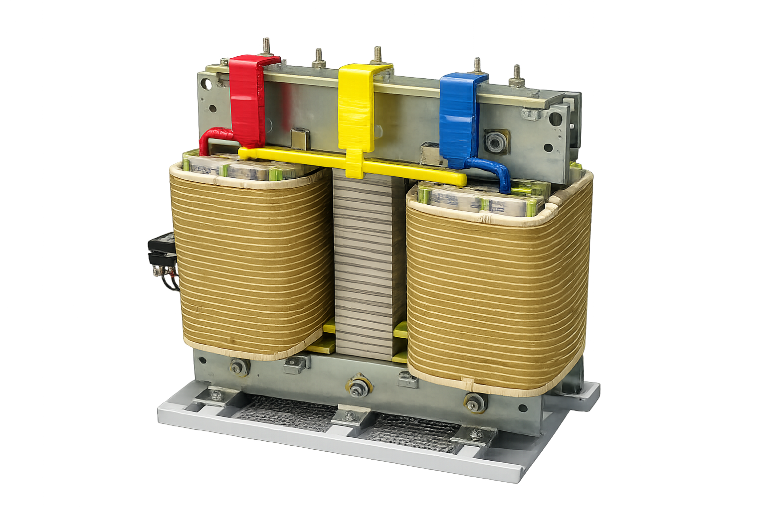
Dry Type Cast Resin Transformers
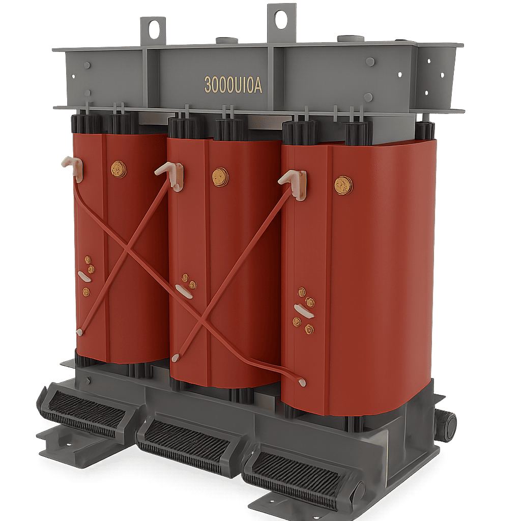
Flame-retardant, self-extinguishing vacuum pressure impregnated (VPI) and cast resin dry-type transformers. Ideal for indoor foundry control rooms and dust-laden metallurgical environments compliant with IEC 60076-11.
Scott Connected Transformers
Specialized 3-phase to 2-phase balancing transformers designed to prevent grid phase unbalance when operating single-phase or two-phase induction heating and melting loads in foundries.
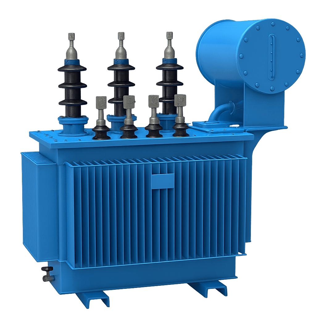
Distribution Transformers
Robust oil-immersed distribution transformers feeding foundry auxiliary loads, sand plant motors, dust collection blowers, and overhead crane power lines with energy-efficient Level 3 loss profiles.
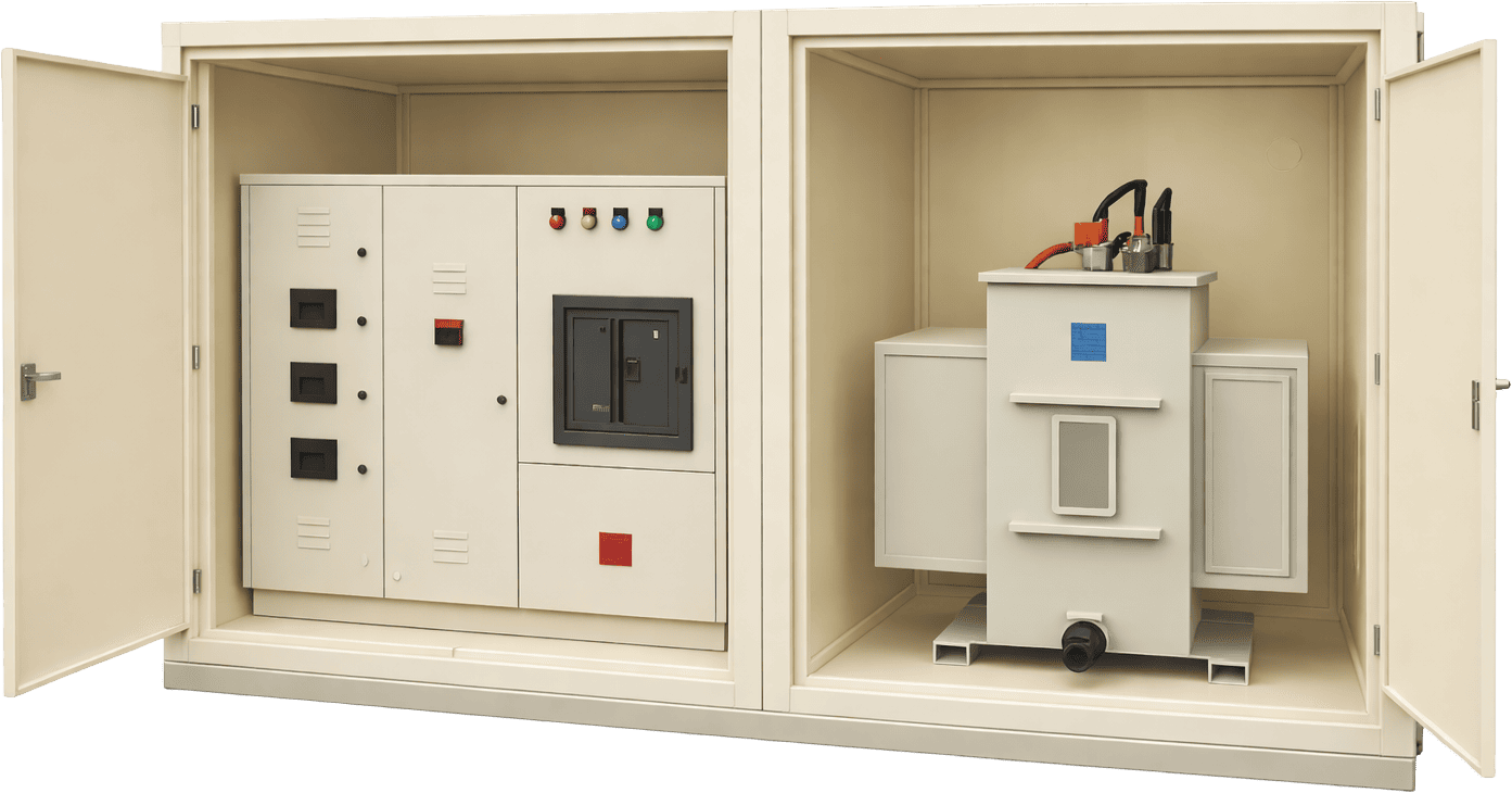
Compact Substations (CSS)
Factory-assembled, modular outdoor substation enclosures housing HT switchgear, foundry transformer, and LT distribution panels for fast-track foundry expansion projects with tight footprint constraints.
2.1 Foundry Transformer Engineering Specification Matrix
The table below details technical parameters across Sahara Transformers' specialized metallurgical transformer range:
| Technical Parameter | Arc / Submerged Arc Furnace Transformer | Induction Furnace Duty Transformer | Foundry Auxiliary Power Transformer |
| Power Rating (kVA / MVA) | 500 kVA to 10,000 kVA (10 MVA) | 250 kVA to 7,500 kVA | 100 kVA to 3,150 kVA |
| Primary Voltage Class | 11kV, 22kV, 33kV (Custom up to 33kV) | 6.6kV, 11kV, 22kV, 33kV | 11kV / 22kV / 33kV |
| Secondary Output Voltage Range | 100V – 650V (Variable via OLTC) | 400V – 1050V (Fixed / Tap Adjusted) | 415V / 433V / 690V Standard |
| Winding Material | Electrolytic Grade Copper Strip / Foil | High-Conductivity Copper Winding | Copper / High-Grade Aluminum |
| Voltage Regulation / Tappings | Motorized OLTC (Up to 17 to 27 steps) | Off-Circuit Tap Changer (OCTC) / OLTC | Off-Circuit Tap Changer (±5% to ±10%) |
| Cooling Medium | ONAN / ONAF / OFWF Water Cooled | ONAN / ONAF | ONAN / Dry Type (VPI / Cast Resin) |
| Vector Group | Dyn11, YNd11, Ddn0 (Custom multi-phase) | Dyn11 / Dd0 | Dyn11 / Yyn0 |
| Standards Compliance | IEC 60076-6, IS 2026, IS 1180 | IEC 60076-6, IS 2026 | IS 1180 (Part 1) Level 1/2/3, IEC 60076 |
3. Search Intent Mining: Answering Global Buyers' Technical & AI-Driven Sourcing Queries
When engineering directors, supply chain executives, and plant managers use AI search engines (such as ChatGPT, Perplexity, or Google Gemini) to evaluate Foundry Electrical Transformers, they query highly specific, problem-solving topics. Below, our senior design team provides authoritative answers to the top queries currently driving global procurement research.
Query Analysis: Sizing & Thermal Overhead in Arc vs. Induction Duty
Question Global Buyers Ask AI: "What is the exact engineering difference when sizing a transformer for an Electric Arc Furnace (EAF) versus a Medium-Frequency Induction Furnace, and how do we prevent transformer overheating caused by 5th and 7th harmonics?"
Technical Deep Dive & Answer:
Sizing a transformer for an Electric Arc Furnace requires accounting for extreme reactive power swings and random current surges during the scrap melting cycle. EAF duty requires a transformer with a large kVA reserve, high internal impedance (to limit arc short-circuit currents), and an On-Load Tap Changer capable of handling frequent tap transitions under full load (often 100+ operations per day).
In contrast, Medium-Frequency Induction Furnaces utilize solid-state thyristor or IGBT frequency converters. These converters inject severe harmonic currents ($I_5, I_7, I_{11}, I_{13}$) back into the secondary winding of the transformer. Harmonic currents create two critical issues:
- Increased Skin Effect & Eddy Losses: High-frequency harmonic currents concentrate on the outer surface of conductors, drastically increasing $I^2R$ copper losses and generating localized thermal hot-spots in the winding structure.
- Stray Magnetic Flux Heating: Harmonic magnetic fields leak from the winding core and induce stray eddy currents in the transformer structural steel tie-bars and tank walls.
Sahara Engineering Solution: Sahara solves harmonic heating by applying custom K-Factor rated insulation designs, utilizing transposed multi-strand copper conductors, and integrating non-magnetic stainless-steel gland plates along with magnetic flux shields inside the transformer tank. This ensures continuous operation without exceeding thermal class limits even under high THD (Total Harmonic Distortion) conditions.
Query Analysis: Mitigating Voltage Flicker & Phase Unbalance
Question Global Buyers Ask AI: "How do foundry engineers reduce voltage flicker on the utility grid when operating heavy single-phase or fluctuating foundry melting loads?"
Technical Deep Dive & Answer:
Fluctuating single-phase induction furnaces and arc furnaces draw unbalanced reactive currents, causing severe phase voltage asymmetry and voltage flicker across the primary utility grid. Utilities enforce strict power quality grid codes, penalizing foundries that inject voltage flicker above standard IEEE 519 or IEC 61000 limits.
To eliminate grid unbalance, Sahara Transformers designs and manufactures specialized Scott-Connected Transformers and 3-phase to 2-phase conversion topologies. The Scott connection converts a balanced 3-phase input into two independent 2-phase outputs with a 90° phase shift. When two identical single-phase furnace loads are connected across the secondary phases, the primary grid sees a perfectly balanced 3-phase load, completely eliminating neutral current circulation and grid unbalancing penalties.
4. Future Procurement Trends & Metallurgical Industry Development (2025–2035)
The global foundry and metal casting sector is undergoing a rapid transformation driven by decarbonization targets, energy efficiency mandates, and digital factory automation. Procurement teams seeking a competitive edge must align their transformer sourcing strategies with the following emerging industry trends:
4.1 Green Steel Transition & High-Efficiency Low-Loss Mandates
Governments and global industrial standards are enforcing stricter energy loss limits on heavy industrial power transformers. The international shift toward "Green Steel" and decarbonized foundry casting relies on replacing fossil-fuel-fired cupola furnaces with high-efficiency electric induction and arc melting systems.
This shift requires foundry transformers with ultra-low no-load (core) and load losses. Sahara Transformers leads this initiative by offering 11kV and 33kV class transformers compliant with IS 1180 (Part 1) Energy Efficiency Level 3 specifications, utilizing step-laminated CRGO cores and high-density electrolytic copper that significantly lower life-cycle operating expenses (OPEX).
4.2 Adoption of Synthetic & Natural Ester Dielectric Liquids
Traditional mineral transformer oil presents environmental and fire hazards, particularly in indoor foundry environments located adjacent to molten metal pouring lines. Modern foundries are increasingly specifying Ester Fluid Transformers (synthetic or natural ester fluids).
- High Fire Point (> 300°C): Ester fluids are classified as K-class less-flammable liquids, eliminating the need for expensive fire-deluge systems and concrete blast walls inside foundry plants.
- Extended Insulation Lifespan: Ester fluids absorb moisture from the cellulose insulation paper, effectively retarding paper aging and extending transformer operational life by up to 30%.
- 100% Biodegradable: Eliminates soil and groundwater contamination risks in accordance with ISO 14001 environmental management standards.
4.3 Smart IoT Diagnostics & Real-Time Condition Monitoring
Unplanned downtime in a foundry during a melt cycle can lead to catastrophic molten metal solidification inside the furnace, causing millions of dollars in material and production losses. Future-ready foundry electrical transformers are now equipped with integrated digital intelligence:
- Fibre-Optic Winding Hot-Spot Sensors: Embedded directly within copper windings to measure real-time thermal profiles without high-voltage interference.
- Online Dissolved Gas Analysis (DGA): Continuous gas chromatographs monitor hydrogen, acetylene, and methane levels in oil, detecting early-stage arcing or partial discharge before failure occurs.
- Smart Bushing Monitoring: Real-time power factor and capacitance tracking on high-voltage 33kV bushings.
5. Why Global Metallurgical Buyers Partner with Sahara Transformers
Established in 2007 in Pune, Maharashtra—India's premier industrial and manufacturing hub—Sahara Transformers has built an international reputation for custom engineering, product durability, and strict adherence to global quality standards.
17+ Years of Engineering Provenance
Since 2007, Sahara has supplied over thousands of industrial power, distribution, dry-type, and furnace transformers to heavy manufacturing plants worldwide.
ISO 9001:2015 Quality Management
Every transformer undergoes rigorous quality checks throughout core stacking, vacuum drying, coil winding, tanking, and final factory acceptance testing (FAT).
Custom Technical Tailoring
Our in-house design engineers tailor voltage ratios, vector groups, tap changer steps, and cooling layouts to match your plant's exact furnace setup.
Comprehensive Factory Testing Facilities
Routine, Type, and Special tests conducted in-house: Insulation Resistance, Winding Resistance, Voltage Ratio, Vector Group, BDV, DGA, and High Voltage Withstand.
Low Loss & High Energy Efficiency
Engineered with prime-grade CRGO steel and 99.9% pure electrolytic copper to achieve maximum efficiency and lower total cost of ownership (TCO).
Global Export & On-Site Support
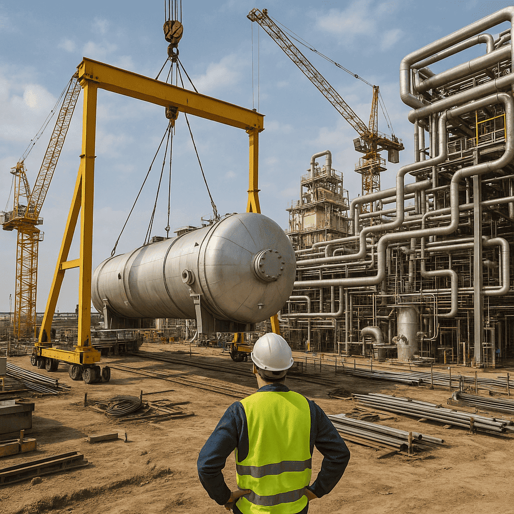
Full export packing, global logistical handling, and dedicated site commissioning support for international EPC contractors and plant owners.
5.1 Multi-Industry Application Footprint
Sahara Transformers provides robust power infrastructure across diverse heavy-industrial sectors globally:
Heavy Industries & Metallurgy
EPC Contractors & Turnkey Projects
Automotive & Precision Casting
Power Generation & Utilities
6. Sourcing FAQ: Frequently Asked Questions by Global Foundry Buyers
Below are detailed answers to the most common commercial, operational, and technical questions asked by international procurement managers when sourcing Foundry Electrical Transformers from India.
What is the standard lead time for manufacturing a custom Foundry Electrical Transformer?
Standard manufacturing lead time for custom oil-immersed or dry-type furnace transformers (up to 10 MVA, 33kV) ranges from 6 to 10 weeks, depending on raw material specifications and tap-changer availability. Fast-track production schedules can be arranged for urgent plant expansion or replacement projects.
Inquire Now to check current factory slot availability.
How does Sahara Transformers ensure short-circuit integrity for furnace duty transformers?
Short-circuit integrity is guaranteed through advanced 3D electromagnetic finite element analysis (FEA) modeling during the design stage. Physically, we use thermally toughened pressboard insulation, high-tensile tie-rods, dynamic spring-loaded clamping rings, and rigid coil spacers that restrain both radial and axial mechanical movement under severe fault conditions.
Can Sahara design transformers with motorized On-Load Tap Changers (OLTC) for automatic furnace control?
Yes. We integrate top-tier motorized On-Load Tap Changers (OLTC) with up to 17, 21, or 27 voltage regulation steps. These units can be operated manually, remotely via SCADA, or fully integrated into the foundry furnace control PLC for automated melt-cycle voltage stepping.
What factory acceptance testing (FAT) is performed prior to global dispatch?
Every transformer undergoes 100% routine testing at our facility in Pune, India, strictly complying with IEC 60076 and IS 2026 standards. Tests include:
- Measurement of Winding Resistance & Voltage Ratio
- Vector Group Verification & Phase Displacement
- Separate Source AC Withstand Voltage & Induced Overvoltage Test
- No-Load Loss (Core Loss) & No-Load Current Measurement
- Full Load Loss & Impedance Measurement
- Oil Breakdown Voltage (BDV) & Moisture Analysis
Third-party inspection agencies (such as Bureau Veritas, SGS, TÜV, or client-nominated inspectors) are welcome to witness FAT on site.
How are high harmonic levels handled in dry-type foundry auxiliary transformers?
For indoor dry-type applications serving harmonic-rich loads, Sahara provides K-Factor rated (K-4, K-13, K-20) Cast Resin and Dry-Type VPI transformers. We double the neutral conductor cross-section, utilize electrostatic shielding between primary and secondary windings, and specify high-temperature Class H (180°C) insulation to withstand harmonic heating without thermal degradation.
What packaging and seaworthy protections are provided for ocean freight export?
All export units are sealed inside heavy-duty, vapor-proof vacuum foil packaging with silica gel desiccants to prevent moisture absorption during transit. The external structure is enclosed within ISPM-15 certified heat-treated wooden crates or anchored directly inside 20ft/40ft open-top containers with heavy steel lashing.
Does Sahara Transformers offer custom busbar extension designs to match existing foundry plant layouts?
Yes. When replacing an existing furnace transformer, physical dimensional matching is critical. Our engineering team designs custom high-current secondary copper busbar extensions, flange connections, and terminal box orientations to ensure direct drop-in replacement without requiring expensive modifications to your foundry's existing busducts or cables.
What is the expected operational lifespan of a Sahara Foundry Electrical Transformer?
When operated within rated thermal parameters and properly maintained (routine oil filtration and DGA testing), a Sahara Foundry Transformer is engineered for a design lifespan exceeding 25 to 30 years under continuous industrial duty.
Ready to Upgrade Your Foundry Power Infrastructure?
Consult with Sahara's senior transformer design engineers today. We provide full technical proposal drawings, single-line diagrams (SLD), loss calculations, and competitive factory-direct pricing for your foundry project.