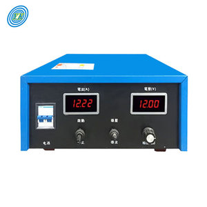
YUCOO Plating Rectifier 220V AC to 12V DC (50A - 1000A) Electroplating Power Supply
AC-DC Switching
1000A Max Ripple Control
Class H Insulation

Engineered to strict ISO, IEC 60076, and IS standards. Explore our high-current, low-temperature rise magnetic solutions optimized for industrial power conversion.
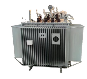
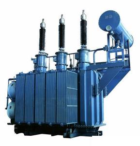
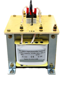
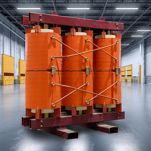
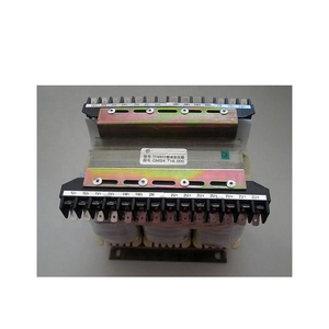
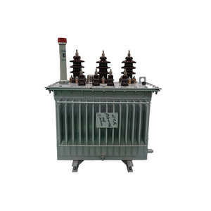
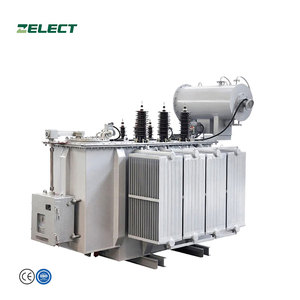
From state-of-the-art Vacuum Pressure Impregnation (VPI) systems to continuous-strip toroidal winding robotics, our integrated manufacturing infrastructure ensures uncompromised electrical security.
We utilize prime-grade, low-loss CRGO silicon steel strips wound continuously without air gaps. This topological advantage eliminates mechanical joint reluctance, reducing core loss ($P_{fe}$) by up to 40% compared to conventional stacked EI laminations.
Due to the symmetrical 360° uniform distribution of copper windings over the closed ring torus, stray magnetic flux leakage is minimized to $< 10\%$ of standard transformers, making our toroidal designs critical for noise-sensitive medical MRI, audio amplifier, and telecom applications.
Engineered for extreme duty cycles. Our toroidal transformers feature double-insulated enamel copper wire coupled with DuPont Nomex® barrier tape and vacuum pressure epoxy impregnation, guaranteeing reliable operation at thermal ratings up to 200°C (Class N).
High-power electroplating, cathodic protection, and traction systems inherently create non-linear load harmonics. Our 6-pulse, 12-pulse, and custom 24-pulse phase-shifted toroidal primary topologies eliminate $5\text{th}$, $7\text{th}$, and $11\text{th}$ order harmonics directly at the source.
Whether requiring low-profile pancake dimensions for space-restricted rack equipment, IP65 waterproof resin-potted modules, or heavy-duty NEMA 4X stainless steel enclosures for harsh galvanic plating shops, our engineering team provides 3D CAD modeling and prototype delivery within 7 business days.
Every transformer undergoes strict routine tests before dispatch, including Turns Ratio Verification, Winding DC Resistance, Induced Overvoltage Testing, Dielectric Breakdown (BDV) up to 10kV, and Automated Partial Discharge Monitoring under full load conditions.
In modern industrial electrical architecture, the demand for energy efficiency (IS 1180 Level 3 / IEC 60076 compliance), spatial footprint reduction, and acoustic hum elimination has propelled the industry-wide migration from legacy rectangular E-I laminated cores toward advanced continuous-wound Toroidal Core Transformer topologies. This whitepaper analyzes the electromagnetic physics, procurement dynamics, and future technological evolution of industrial toroidal transformer systems.
The core efficiency of any magnetic transformer is fundamentally constrained by its magnetic flux path symmetry and material domain orientation. Traditional E-I stacked laminations introduce microscopic air gaps at the mechanical joints where the 'E' and 'I' stampings interface. These air gaps create high magnetic reluctance ($\mathcal{R}$), leading to increased magnetizing current ($I_m$), stray flux leakage, and audible magnetostrictive vibration (hum).
Conversely, a true Toroidal Transformer is constructed by tightly winding a continuous ribbon of Cold-Rolled Grain-Oriented (CRGO) high-silicon electrical steel under controlled mechanical tension. Because the grain structure of the steel aligns 100% with the natural circular direction of the magnetic flux path ($\Phi$), the core achieves an exceptionally high permeability ($\mu$) and near-zero magnetic reluctance.
When feeding high-current electroplating rectifiers (e.g., 220V AC to 12V DC at 1000A) or heavy traction drives, rectifying semiconductor elements (thyristors/IGBTs) generate sharp current impulses. Toroidal transformers exhibit superior leakage inductance control ($L_{lk}$), preventing voltage sag while maintaining linear magnetic response under heavy DC bias conditions.
As global industrial supply chains pivot toward decarbonization, strict energy efficiency standards, and smart grid automation, industrial procurement directors must evaluate the following four emerging trends in power transformer technology:
While CRGO steel remains the industrial workhorse, next-generation toroidal transformers are adopting Nanocrystalline core ribbon alloys. Operating at saturation flux densities exceeding 1.2 Tesla with ultra-thin ribbon thickness ($25\,\mu\text{m}$), nanocrystalline cores yield negligible eddy-current losses, permitting switching frequencies up to 50 kHz for high-frequency switching rectifiers.
For high-capacity liquid-immersed rectifier transformers (e.g., 6300kVA cathodic protection and substation units), global procurement mandates are shifting away from mineral oil toward synthetic and natural ester fluids. Vegetable-based ester oils offer a flash point $> 300^\circ\text{C}$ (Class K rating) and 100% biodegradability within 28 days.
Modern industrial procurement increasingly specifies embedded fiber-optic thermal sensors and RS-485 Modbus telemetry directly inside toroidal winding stacks. Real-time Dissolved Gas Analysis (DGA) and hot-spot temperature tracking allow predictive maintenance algorithms to calculate remaining insulation lifetime dynamically.
Regulatory frameworks such as IEEE 519-2022 enforce strict grid THD limits. Toroidal rectifier transformers utilizing extended secondary phase-shifting configurations (such as extended delta $\pm 7.5^\circ$) enable 24-pulse ripple cancellation, eliminating the need for bulky external passive harmonic filter banks.
Quantitative performance metrics comparing Toroidal Transformer technology against conventional Dry-Type Cast Resin, EI Laminated, and Oil-Immersed systems.
| Performance Benchmark Metric | CRGO Toroidal Transformer | EI-Laminated Transformer | Cast Resin Dry-Type | Oil-Immersed Power Station |
|---|---|---|---|---|
| Operating Energy Efficiency (%) | 98.2% – 99.4% | 91.0% – 94.5% | 95.5% – 97.8% | 98.5% – 99.2% |
| Magnetic Stray Field Radiation (mT) | < 0.15 mT (Negligible) | 1.5 – 3.0 mT (High) | 0.8 – 1.2 mT (Moderate) | 0.5 – 1.0 mT (Moderate) |
| No-Load Iron Loss ($P_{fe}$) | Ultra-Low (Continuous Strip) | High (Air-gap reluctance) | Moderate-Low | Very Low |
| Acoustic Noise Floor (dBA) | < 32 dBA (Whisper-Quiet) | 55 – 68 dBA (Vibrational Hum) | 45 – 52 dBA | 48 – 58 dBA |
| Physical Weight / Footprint Ratio | Baseline (-50% vs EI) | +100% Heavier | +65% Larger Envelope | +140% Larger Footprint |
| Thermal Insulation Ceiling | Class H (180°C) / N (200°C) | Class B (130°C) / F (155°C) | Class F (155°C) / H (180°C) | Class A (105°C Liquid) |
| Inrush Current Multiplier ($I_{inrush}/I_n$) | 10x – 15x (Requires Soft Start) | 4x – 8x | 8x – 12x | 6x – 10x |
| Harmonic Tolerance Factor (K-Factor) | Up to K-20 Rated | K-4 to K-9 Max | Up to K-13 | Up to K-13 |
Expert solutions for electrical engineers, system integrators, and OEM procurement managers.
High-current AC-to-DC electroplating rectifiers can impose asymmetrical DC offset components on the secondary winding. In custom-engineered toroidal transformers, we mitigate DC saturation by utilizing high-coercivity CRGO core alloys combined with precise secondary copper cross-sectional balancing. This prevents the B-H hysteresis curve from shifting into magnetic saturation, preserving linear inductance even during 100% duty cycle 1000A plating discharges.
Because continuous toroidal cores possess high magnetic remanence ($B_r$) and zero air gap reluctance, energizing the primary winding at the peak of the AC voltage wave can produce a momentary magnetizing inrush current ($10\text{x}$ to $15\text{x}$ rated nominal current). This is easily handled in industrial control panels using negative temperature coefficient (NTC) thermistors, soft-start resistor-relay circuits, or delayed-trip circuit breakers (Type D curve).
Our standard production line builds to Class F ($155^\circ\text{C}$) insulation. However, for extreme duty applications such as metallurgical furnace controls, underground traction stations, or sealed non-ventilated enclosures, we build custom Class H ($180^\circ\text{C}$) and Class N ($200^\circ\text{C}$) units utilizing double polyamide-coated magnet wire and high-grade silicone impregnation.
Yes. We specialize in custom OEM manufacturing. Primary windings can be configured for global dual-voltage inputs (e.g., 110V/220V AC or 380V/415V/480V 3-Phase). Secondary windings can feature isolated step-down outputs ranging from high-current low-voltage (6V, 12V, 24V, 48V, 60V DC rectifiers) to multi-kilovolt traction and step-up substation supplies.
Every export shipment is accompanied by full Factory Acceptance Test (FAT) documentation, including: Resistance Measurement of windings, Voltage Ratio & Vector Group Check, Impedance Voltage & Load Loss Test, No-Load Loss & Current Test, Separate-Source Voltage Withstand Test, Induced Overvoltage Test, and CE / ISO Compliance Certificates.
Standard engineered prototypes are delivered within 7 to 10 business days following 3D CAD drawing approval. Full production runs (from 100 to 5,000 units) typically ship within 3 to 4 weeks depending on raw material core specifications and custom enclosure fabrication requirements.