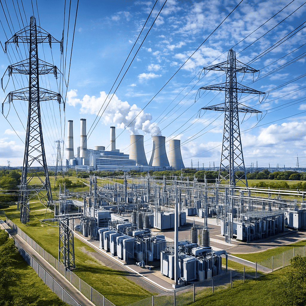
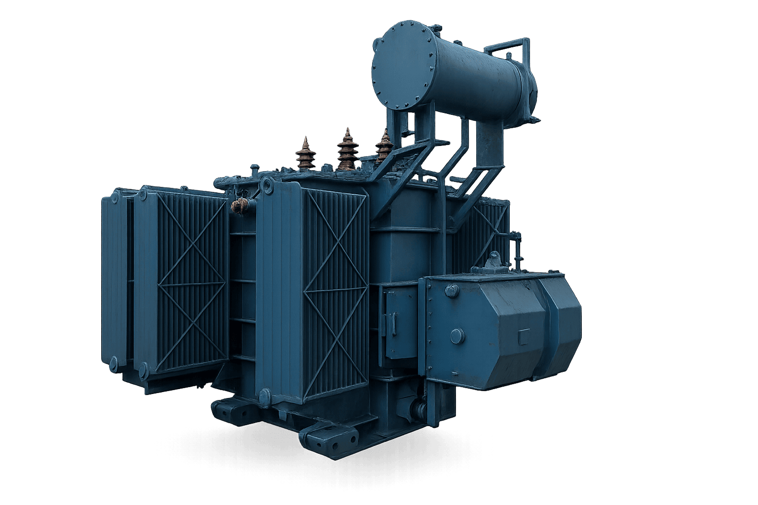
Global Power & Rectifier Transformer Procurement Trends (2025–2035)
The global power transformer market is undergoing an unprecedented structural transition driven by grid modernization, the expansion of utility-scale renewable energy storage, green hydrogen electrolysis, and the electrification of industrial heavy manufacturing. B2B procurement managers and lead electrical engineers are moving away from standard off-the-shelf catalog units toward highly customized OEM/ODM Power Transformer Engineering designed for specific harmonic spectrums, thermal stresses, and aggressive duty cycles.
According to international energy infrastructure benchmarks, industrial power grids encounter up to 40% higher non-linear load demands compared to two decades ago. This expansion is heavily influenced by the proliferation of Variable Frequency Drives (VFDs), mega-ampere DC electroplating lines, electric arc furnaces (EAF), and traction power substations. As a consequence, purchasing decisions are no longer governed solely by initial Capital Expenditure (CapEx); the total lifetime Operational Expenditure (OpEx)—dictated by core loss levels, thermal dissipation capabilities, and mean time between failures (MTBF)—now serves as the primary evaluation metric in B2B technical tenders.
Decarbonization & Eco-Loss Standards
Stricter global energy efficiency regulations (such as EU Ecodesign Tier 2 and IS 1180 Level 3 mandates) force plants to specify ultra-low loss amorphous metal or high-permeability grain-oriented silicon steel cores.
Harmonic Mitigation & Duty-Cycle Resilience
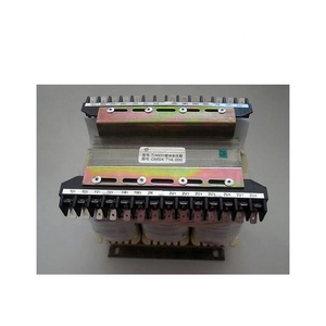
Modern rectifier transformers require advanced phase-shifting secondary windings (12-pulse, 24-pulse, and 48-pulse systems) to cancel low-order harmonics directly at the power conversion interface.
Custom OEM Flexibility & Direct Sourcing
Procurement directors favor direct-from-factory OEM partners capable of engineering unique voltage ratios, specialized tap-changer integration, and custom physical enclosure dimensions.
Engineering Excellence: Rectifier & Industrial Power Transformer Technology
Rectifier transformers are technically distinct from standard distribution transformers. They must withstand severe electromagnetic forces, high current ripple factors, and intense thermal stress caused by non-sinusoidal current waveforms. As a dedicated OEM/ODM manufacturer, our design philosophy incorporates several core engineering innovations:
1. Phase-Shifting Winding Configurations & Harmonic Attenuation
To reduce the total harmonic distortion (THD) injected into the primary high-voltage grid, our multi-pulse rectifier transformers utilize extended-delta, star-delta, or zig-zag winding arrangements. By introducing precise electrical phase shifts (e.g., ±15° for 12-pulse systems, ±7.5° for 24-pulse systems), low-order harmonics such as the 5th, 7th, 11th, and 13th are naturally canceled within the magnetic circuit, eliminating the need for bulky external passive filters.
2. Thermal Management & K-Factor Rated Insulation
Harmonic eddy current losses in windings can cause severe localized hot spots. We utilize high-grade Nomex insulation paper, Class H epoxy resin encapsulation for dry-type models, and optimized natural/forced oil circulation channels (ONAN/ONAF/OFAF) for liquid-immersed units. Every transformer is custom K-factor rated (K-4, K-9, K-13, K-20) based on the calculated harmonic spectrum of the customer's load profile.
3. Mechanical Short-Circuit Withstand Capability
Rectifier circuits in electroplating, cathodic protection, and traction systems frequently experience sudden load short-circuits. Our core and coil assemblies feature heavy-duty axial hydraulic clamping plates, high-density pressboard spacers, and double-paper-covered electrolytic copper conductors capable of enduring dynamic short-circuit forces exceeding IEC 60076-5 stress thresholds.
Primary Industrial Transformer Categories
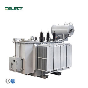
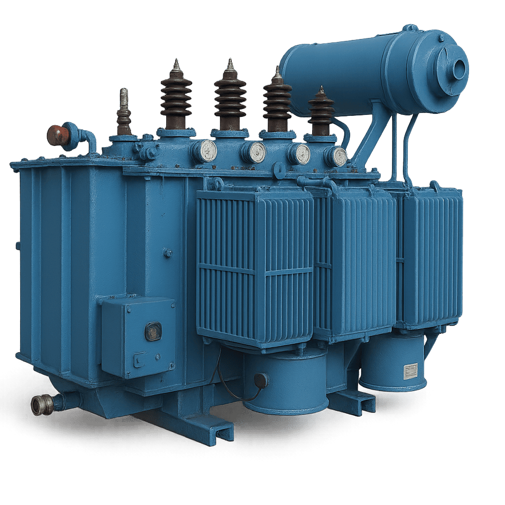
High-Voltage Power Transformers
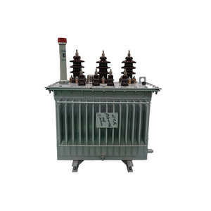
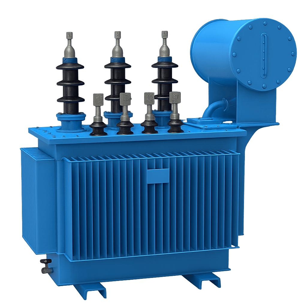
Electric Distribution Transformers
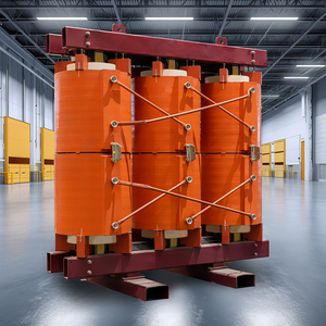
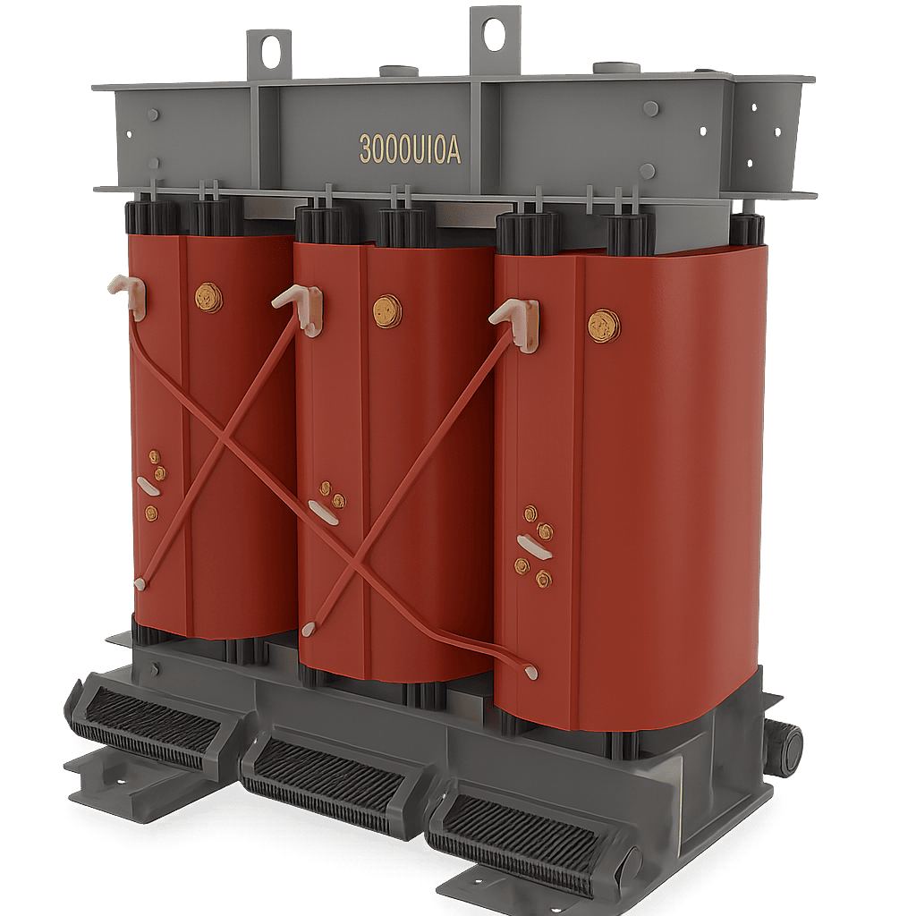
Epoxy Cast Resin Dry-Type
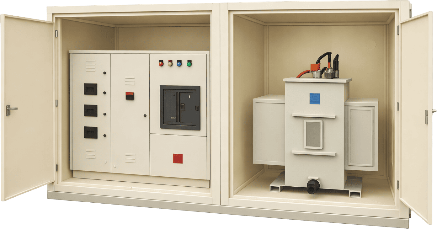
Compact Substation Units (CSS)
Technical Data Matrix: IS 1180 / IEC 60076 Loss Standards
To assist engineering teams in verifying efficiency metrics, the table below provides standardized maximum total energy loss values across various kVA ratings for 11kV Class Distribution & Industrial Step-Down Transformers under IS 1180 (Part 1) Amendment No. 1 specifications:
| Sl. No. |
Rating (kVA) |
Impedance (%) |
Maximum Total Losses (Watts) |
| Energy Efficiency Level 1 |
Energy Efficiency Level 2 |
Energy Efficiency Level 3 (Ultra-Low Loss) |
| 50% Load |
100% Load |
50% Load |
100% Load |
50% Load |
100% Load |
| 1 | 250 kVA | 4.50% | 1050 W | 3150 W | 980 W | 2930 W | 920 W | 2700 W |
| 2 | 315 kVA | 4.50% | 1100 W | 3275 W | 1025 W | 3100 W | 955 W | 2750 W |
| 3 | 400 kVA | 4.50% | 1300 W | 3875 W | 1225 W | 3450 W | 1150 W | 3330 W |
| 4 | 500 kVA | 4.50% | 1600 W | 4750 W | 1510 W | 4300 W | 1430 W | 4100 W |
| 5 | 630 kVA | 4.50% | 2000 W | 5855 W | 1860 W | 5300 W | 1745 W | 4850 W |
| 6 | 800 kVA | 5.00% | 2459 W | 7300 W | 2287 W | 6402 W | 2147 W | 5837 W |
| 7 | 1000 kVA | 5.00% | 3000 W | 9000 W | 2790 W | 7700 W | 2620 W | 7000 W |
| 8 | 1250 kVA | 5.00% | 3600 W | 10750 W | 3300 W | 9200 W | 3220 W | 8400 W |
| 9 | 1600 kVA | 6.25% | 4500 W | 13500 W | 4200 W | 11800 W | 3970 W | 11300 W |
| 10 | 2000 kVA | 6.25% | 5400 W | 17000 W | 5050 W | 15000 W | 4790 W | 14100 W |
| 11 | 2500 kVA | 6.25% | 6500 W | 20000 W | 6150 W | 18500 W | 5900 W | 17500 W |
* Note: Custom impedance values, alternative voltage classes (e.g., 22kV, 33kV, 66kV), and specialized rectifier secondary taps are fully engineered upon OEM design request.
Why Partner with Us: Manufacturing Supremacy & ISO Quality Control
Established with over 17 years of specialized experience in industrial transformer manufacturing, our facility combines automated core-stacking machinery, vacuum pressure impregnation (VPI) plants, and fully equipped high-voltage testing laboratories. We provide end-to-end OEM and ODM services for international clients requiring stringent adherence to global electrical norms.
100% Factory Acceptance Testing (FAT)
Every transformer undergoes routine testing including winding resistance, voltage ratio, phase displacement, no-load loss, full-load loss, impedance voltage, and dielectric withstand tests before dispatch.
Type-Tested Design Compliance
Our core designs possess full type-test certifications for lightning impulse voltage withstand, temperature rise limits, and dynamic short-circuit withstand capabilities from accredited independent labs.
Custom Co-Engineering Support
Our in-house electrical design engineers collaborate directly with project contractors, providing CAD dimensional drawings, 3D STEP models, and electrical loss calculations prior to production.
Global Industry Footprint & Deployment Sectors
Our OEM/ODM transformer solutions power critical operations across diverse industrial sectors worldwide:
Power Generation & Distribution Utilities
Solar & Renewable Energy Plants
Oil, Gas & Petrochemical Plants
Metallurgical & Smelting Operations
Engineering & Automotive Factories
Hospitals, Data Centers & IT Infrastructure
Turnkey EPC Electrical Projects
Rail Transit & Infrastructure
Frequently Asked Questions (B2B Procurement & Engineering)
Addressing crucial technical, commercial, and operational queries raised by global procurement personnel and engineering leads:
What is the technical difference between a standard distribution transformer and a rectifier transformer?
A standard distribution transformer feeds linear AC loads with sinusoidal current. A rectifier transformer directly supplies solid-state rectifiers (diodes/thyristors) feeding DC loads. Consequently, rectifier transformers are engineered with specialized phase-shifting secondary windings, increased mechanical clamping to withstand short-circuit forces, heavy electromagnetic shielding, and K-factor insulation ratings to manage severe harmonic heating.
What lead times can be expected for custom OEM/ODM transformer orders?
Standard production lead times range between 3 to 6 weeks depending on kVA capacity, voltage class, and tap-changer complexity. Prototype design verification drawings are submitted within 5 to 7 business days following contract confirmation. Accelerated fast-track manufacturing slots are available for emergency industrial utility projects.
How do you ensure compliance with regional efficiency standards like IS 1180 or IEC 60076?
We utilize advanced computer-aided magnetic field simulation software to optimize core geometry and conductor cross-sections. Combined with high-grade Cold-Rolled Grain-Oriented (CRGO) steel or amorphous metal alloys, our transformers are guaranteed to meet or exceed IS 1180 Level 1, 2, or 3 maximum total loss thresholds.
Can you custom-build transformers for severe environmental conditions?
Yes. We specialize in custom enclosures engineered up to IP65 / NEMA 4X ratings. For offshore, chemical plant, or tropical environments, units feature anti-corrosive C4/C5 grade polyurethane paint finishes, hermetically sealed tanks, stainless steel hardware, and high-altitude/high-ambient temperature cooling radiators.
Do you support third-party inspection (TPI) prior to shipment?
Absolute transparency is integral to our quality assurance. We regularly host international third-party inspection agencies such as Bureau Veritas, SGS, TUV, and Intertek for full Factory Acceptance Testing (FAT) witness procedures in our testing facilities.
What documentation package accompanies each transformer export order?
Every unit is dispatched with a comprehensive quality dossier containing Routine Test Certificates, Material Mill Certificates, Warranty Certificates, CAD Layout & Schematic Drawings, and detailed Installation, Operation & Maintenance (IOM) Manuals.