
High-Performance OEM/ODM Transformer Solutions
Engineered to rigorous IEEE C57 & IEC 60076 standards, delivering short-circuit withstand performance, harmonic mitigation, and low-loss operational efficiency.
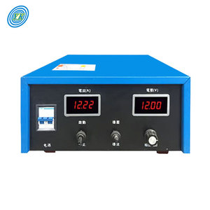
YUCOO Plating Rectifier 220V AC to 12V DC Electroplating Unit
Precision-controlled industrial plating rectifier rated from 50A to 1000A continuous output. Designed for heavy electroplating, anodizing, and electrolysis.
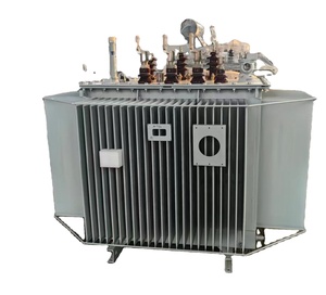
Three-Phase Control Electrical Rectifier Transformer
Heavy-duty 3-phase industrial control rectifier transformer featuring extended delta phase-shifting to minimize network harmonic distortion.
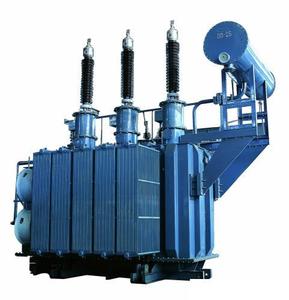
Oil-Immersed High Current 6300kVA Cathodic Protection Transformer
Ultra-high capacity 6300kVA liquid-filled rectifier unit engineered for continuous duty in cathodic protection, metallurgy, and severe ambient conditions.
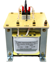
Single-Phase Control Step-Down Rectifier Transformer (2kVA - 5kVA)
Multi-tap primary step-down transformer providing regulated DC/AC secondary outputs (6V to 60V). Ideal for industrial control cabinets and automation.
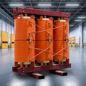
CEEG ZQSC(H)B Series 2000kVA/10kV Epoxy Cast Traction Rectifier
Dry-type cast resin traction rectifier transformer built for municipal rail and electrified transport. Flame-retardant, maintenance-free IEC 60076-11 compliant design.
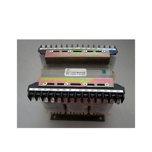
T6 Power Rectifier Transformer TI16933 for Generator Excitation
OEM replacement excitation rectifier transformer specialized for power plant synchronous generator excitation systems (Hyundai HFC6 compatible).
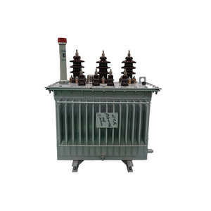
High Voltage 33kV / 1MW Hermetically Sealed Rectifier Transformer
Industrial-grade 33kV high-voltage step-down rectifier transformer. Hermetically sealed oil preservation tank prevents dielectric oil degradation and moisture ingress.
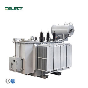
3-Phase Step-Up/Step-Down Rectifier Transformer (50kVA - 3000kVA)
Versatile modular distribution rectifier transformer platform available in ratings up to 3000kVA. Engineered for industrial motor drives, mining, and power substations.
OEM/ODM Manufacturing Authority Since 2007
Combining over 17 years of specialized transformer manufacturing experience with rigorous ISO quality management systems to serve global utilities, EPC contractors, and industrial buyers worldwide.
Zero-Sequence Protection
Specialized Zigzag (Znyn) and neutral grounding transformer designs engineered to absorb single line-to-ground fault currents ($I_0$) while keeping continuous zero-sequence losses to absolute minimums.
Multi-Pulse Harmonic Suppression
Custom 6-pulse, 12-pulse, 18-pulse, and 24-pulse phase-shifted rectifier transformers constructed with extended delta windings to eliminate 5th, 7th, 11th, and 13th order harmonics.
Bespoke OEM/ODM Customization
Full engineering flexibility covering specific primary/secondary voltage ratios, custom vector groups, K-factor ratings (K-13 to K-20), oil-immersed ONAN/ONAF, or dry-type VPI and Cast Resin insulation.
Grounding & Rectifier Transformer Engineering Trends
An in-depth technical analysis of core topology, thermal management, zero-sequence impedance control, and next-generation power grid integration.
1. Zero-Sequence Impedance ($Z_0$) Control in Zigzag Windings
In ungrounded delta electrical distribution networks (common in medium-voltage industrial substations), single line-to-ground (SLG) faults pose severe operational risks, including destructive transient overvoltages caused by arcing grounds. A Grounding Transformer (Neutral Grounding Transformer) provides an artificial neutral point to anchor the system voltage and provide a controlled path for earth fault currents.
The predominant winding configuration used by high-reliability OEM manufacturers is the Zigzag (Zn) topology. In a Zigzag winding, each limb of the magnetic core carries two coils belonging to different phases wound in opposite directions. Under normal balanced three-phase operating voltages, the magnetic flux produced by one half of the winding cancels out the flux produced by the adjacent phase half, resulting in near-infinite positive and negative sequence impedance ($Z_1, Z_2$). Continuous magnetizing current remains extremely low (typically < 0.5% of rated full-load current).
However, during an asymmetrical single line-to-ground fault, the zero-sequence currents ($I_0$) flow in phase through all three windings. Because the currents in the two halves of the winding on each core leg flow in opposite physical directions, their zero-sequence MMFs (magnetomotive forces) oppose each other, yielding a very low internal zero-sequence impedance ($Z_0$). Advanced OEM design optimization focuses on tailoring this $Z_0$ parameter to precisely match system short-circuit requirements and limit fault current duration without saturating the CRGO (Cold-Rolled Grain-Oriented) silicon steel core.
2. Multi-Pulse Phase-Shifting & Harmonic Suppression
Industrial power supplies driving heavy electroplating lines, green hydrogen electrolyzers, variable frequency drives (VFDs), and electric traction systems utilize thyristor or diode bridge rectifiers. These non-linear loads inject high levels of current harmonics back into the primary medium-voltage supply grid, generating voltage distortion, transformer thermal overheating, and capacitor bank degradation.
To overcome harmonic pollution without relying solely on large passive LC filters, state-of-the-art ODM rectifier transformers employ Multi-Pulse Phase-Shifting Architectures:
- 12-Pulse Systems: Utilizing dual secondary windings (Delta and Wye) connected to two bridge rectifiers in parallel or series. This introduces a $30^\circ$ phase shift between secondary voltages, theoretically cancelling the 5th and 7th harmonic currents ($6k \pm 1$).
- 24-Pulse Systems: Utilizing quadruple secondary windings with extended delta phase-shifting coils introducing $\pm 15^\circ$ or $7.5^\circ$ phase offsets. This configuration eliminates the 5th, 7th, 11th, and 13th harmonics, reducing Total Harmonic Distortion (THD) of the input current to below 4.5% in compliance with IEEE 519 standards.
Engineering these multi-winding systems demands rigorous electromagnetic symmetry across all secondary channels to prevent circulatory currents and uneven current sharing among rectifier bridges.
3. Advanced Insulation Materials & Thermal Endurance
Rectifier transformers suffer from additional stray eddy current losses ($P_{EC}$) and stray load losses ($P_{OS}$) caused by non-sinusoidal harmonic currents. The effective winding losses scale according to the square of the harmonic order ($h^2$). As a result, standard transformer insulation systems degrade prematurely under continuous high K-factor loading.
Modern OEM engineering integrates high-temperature insulation media to withstand these elevated thermal stresses:
- Dry-Type VPI & Cast Resin: Utilizing Class H ($180^\circ\text{C}$) or Class C ($220^\circ\text{C}$) Nomex paper and epoxy resins injected under vacuum pressure impregnation (VPI) for superior mechanical rigidity against short-circuit forces.
- High-Flashpoint Liquid Dielectrics: Transitioning from conventional mineral oil to synthetic ester fluids (IEC 61099 compliant) or high-viscosity natural esters, elevating fire flashpoints from $140^\circ\text{C}$ to over $300^\circ\text{C}$ for indoor substations and underground installations.
4. Smart Substation Integration & IoT Monitoring
The transformation of industrial power infrastructure into Industry 4.0 smart grids requires grounding and rectifier transformers equipped with intelligent sensing arrays. Sensor-embedded transformer architectures continuously stream telemetry to SCADA and cloud platform systems:
- Dissolved Gas Analysis (DGA): Multi-gas optical sensors tracking dissolved Hydrogen ($H_2$), Acetylene ($C_2H_2$), and Methane ($CH_4$) levels to detect early-stage partial discharge or thermal hotspots.
- Fibre-Optic Winding Temperature Sensors: GaAs-based direct optical fiber sensors embedded within inner winding turns to provide instantaneous hotspot temperature measurement without electrical interference.
- Real-Time Zero-Sequence Neutral Monitoring: CT arrays tracking continuous neutral current drift and earth resistor degradation to prevent ungrounded system failures.
Future Procurement Trends for Grounding & Rectifier Systems
Key market vectors shaping global buyer procurement strategies over the next decade (2025–2035).
Renewable Microgrid Integration
As utility grids incorporate massive photovoltaic arrays and battery energy storage systems (BESS), the demand for multi-functional grounding-inverter transformers has surged. Microgrids operating in islanded mode require fast-acting neutral grounding transformers with integral auxiliary windings to maintain system neutral reference and feed substation local controls.
Green Hydrogen & Megawatt Electrolysis
The rapid expansion of Proton Exchange Membrane (PEM) and Alkaline water electrolysis plants requires giant low-voltage high-current (LVHC) rectifier transformers. Procurement specifications are prioritizing ultra-high current outputs (exceeding 20,000 Amps DC) coupled with high energy efficiency to lower per-kilogram green hydrogen production costs.
Total Cost of Ownership (TCO) Shift
Industrial EPC buyers are shifting evaluation metrics from initial Capital Expenditure (CAPEX) to lifetime TCO models. Under stringent energy performance standards such as IS 1180 Amendment 1 Level 3 and IEC 60076-20 efficiency tiers, specifying low-loss amorphous metal cores and high-grade CRGO magnetic steel yields massive long-term OPEX savings over a 30-year lifecycle.
Frequently Asked Questions (FAQ) for B2B Buyers
Expert engineering answers to critical questions encountered during specification, sizing, and global procurement of grounding and rectifier transformers.
The zero-sequence impedance ($Z_0$) of a Zigzag grounding transformer is calculated based on the maximum allowable ground fault current ($I_{g}$) requested by the system protection study and the continuous system line-to-neutral voltage ($V_{LN}$):
$$Z_0 = \frac{3 \times V_{LN}}{I_g} - 3 Z_N$$
where $Z_N$ is the impedance of the Neutral Grounding Resistor (NGR) if connected between the neutral point and earth. Grounding transformers are typically rated for short-time duration rather than continuous power output. Common standard rating durations per IEEE C57.32 are 10 seconds, 30 seconds, or 60 seconds under continuous full fault current ($I_{fault}$). The equivalent continuous thermal kVA rating is usually only 3% to 10% of its short-time rating, making Zigzag units significantly more compact and cost-effective than standard 3-phase two-winding transformers of equivalent short-circuit kVA capacity.
While both are specialized magnetics, their core electromagnetic functions differ fundamentally:
- Grounding Transformers: Primary role is to establish an artificial zero-sequence reference point for ungrounded 3-phase delta systems. They carry negligible current under normal operation and must sustain extreme zero-sequence thermal stresses during short-duration ground faults.
- Rectifier Transformers: Designed for continuous energy conversion driving AC-to-DC rectifiers. They feature multi-phase secondary windings, high K-factor thermal withstand capability, heavy copper busbar bracing to resist severe magnetic forces, and strict phase-displacement tolerances ($0^\circ, 15^\circ, 30^\circ$) for harmonic cancellation.
Non-linear rectifier loads draw non-sinusoidal currents containing high-frequency harmonics. Higher harmonic frequencies cause disproportionate eddy current heating in primary and secondary conductors ($P_{ec} \propto h^2$). A standard distribution transformer operating under high harmonic loading will experience rapid insulation thermal breakdown.
The K-Factor rating quantifies a transformer's ability to operate safely with non-sinusoidal load currents without exceeding temperature rise limits. OEM rectifier transformers are specifically designed with K-Factor ratings of K-9, K-13, or K-20. This is achieved using transposed conductors (CTC - Continuously Transposed Cable), double-sized neutral conductors, and specialized electrostatic shields between windings to shunt high-frequency noise to earth.
Short-circuit failure is the leading cause of field transformer burnout. Our OEM manufacturing facility validates mechanical strength through rigorous electromagnetic finite element analysis (FEA) during design, followed by physical short-circuit testing at accredited independent testing laboratories (such as KEMA, CPRI, or ERDA).
During Factory Acceptance Testing (FAT), core-and-coil assemblies undergo routine tests including Winding Resistance, Voltage Ratio & Vector Group Verification, Short-Circuit Impedance measurement, Insulation Resistance (IR), Separate-Source AC Voltage Withstand, and Induced Overvoltage Withstand tests.
We provide comprehensive custom engineering tailored to client project requirements, including:
- Voltage Ratings: Primary inputs from 3.3kV up to 33kV; custom low-voltage secondary outputs tailored for thyristor/diode bridges (e.g., 12V, 24V, 48V, 110V, 400V, 690V, 1000V).
- Cooling Modes: ONAN (Oil Natural Air Natural), ONAF (Oil Natural Air Forced), AN (Air Natural dry-type), or AF (Air Forced dry-type).
- Enclosures & Accessories: IP23 to IP65 protective enclosures, stainless steel tanks for offshore/corrosive chemical plants, integrated Neutral Grounding Resistors (NGRs), Off-Circuit Tap Changers (OCTC), or On-Load Tap Changers (OLTC).
In ungrounded distribution systems, when an intermittent line-to-ground arc occurs (arcing ground), system line-to-ground capacitance can charge to destructive voltage levels—sometimes exceeding 3 to 5 times nominal voltage—due to capacitive energy trapping. By installing a Zigzag grounding transformer connected to an appropriately sized neutral grounding resistor, the trapped capacitive charge is dissipated through the neutral resistor during current zero-crossings. This completely dampens system resonance and clamps transient overvoltages to safe operational levels.
Comprehensive Factory Inspection & Testing Protocols
Every single unit undergoes multi-stage quality gates before dispatch to guarantee 100% operational reliability upon field commissioning.
1. Routine Acceptance Tests
Executed on 100% of manufactured units prior to shipment:
- Measurement of winding resistance & voltage turns ratio
- Phase displacement & vector group check
- Measurement of no-load loss ($P_0$) & no-load current
- Measurement of load loss ($P_k$) & short-circuit impedance
- Separate-source AC voltage withstand test
- Induced overvoltage withstand test
2. Type & Special Tests
Performed upon customer specification or design validation:
- Full-wave lightning impulse voltage withstand test
- Temperature rise test ($DT$) under rated loading
- Measurement of zero-sequence impedance ($Z_0$) on Zigzag units
- Acoustic noise level measurement (dB)
- Partial discharge measurement on Cast Resin dry-type units
- Short-circuit withstand capability certification
3. Export Packaging & Logistics
Built to endure international sea freight and rugged site handling:
- Seaworthy heavy-duty vacuum-sealed timber crating
- Desiccant silica gel moisture protection
- Impact & tilt monitoring sensors on high-MVA units
- Complete export documentation (CO, Form E, FAT Reports)