
Industrial Current & Rectifier Transformer Product Line
Explore our ISO-certified, IEC/IEEE-compliant OEM and ODM transformer engineering configurations designed for heavy-duty electroplating, cathodic protection, traction networks, and high-voltage grid metering.
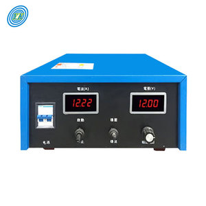
YUCOO Plating Rectifier 220V AC to 12V DC 50A-1000A Electroplating Rectifier
High-precision industrial rectifier unit engineered for heavy-duty electroplating, anodizing, and electrolysis processes with ultra-low ripple voltage.
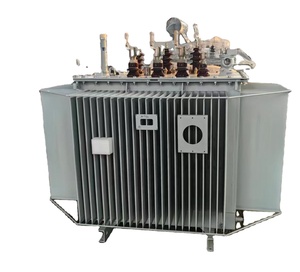
Three Phase Control Electrical Rectifier Transformer
Factory-direct heavy-duty industrial step-down control rectifier transformer featuring reinforced copper windings and thermal overload protection.
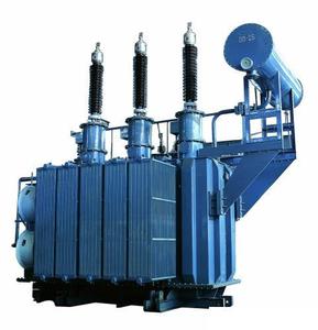
Oil Immersed High Current 6300kVA Cathodic Protection Rectifier Transformer
High-capacity liquid-immersed transformer optimized for continuous high-current cathodic protection in marine, pipeline, and refinery infrastructure.
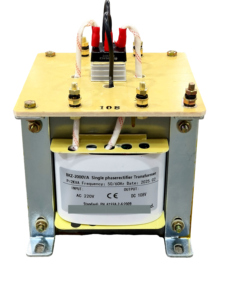
380V/220V to 60V-6V Single-Phase Control Rectifier Transformer (2000VA-5KVA)
Multi-tap step-down isolation control transformer designed for electrical automation cabinets, DC motor excitation, and laboratory power conversion.
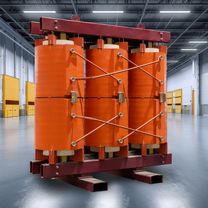
CEEG ZQSC(H)B Series 2000kVA/10kV Epoxy Cast Dry-Type Traction Rectifier Transformer
Flame-retardant, resin-encapsulated dry-type rectifier transformer custom engineered for urban rail transit, subways, and mining electrification.
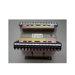
Original T6 Electric Power Rectifier Transformer TI16933 for Excitation Systems
Specialized excitation power rectifier transformer engineered for generator static excitation systems, guaranteeing rapid transient response and stability.
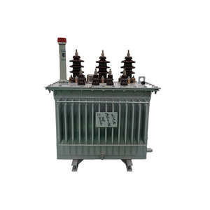
33kV High Voltage 160kVA-1MW Sealed Power Rectifier & Potential Transformer
Fully sealed medium-to-high voltage transformer designed for industrial stepping down, sub-station distribution, and heavy DC conversion loops.
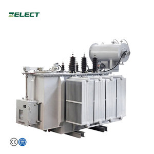
50kVA–3000kVA Industrial 3-Phase Step-Up Rectifier & Distribution Transformer
Versatile step-up/step-down heavy power transformer customized for industrial manufacturing plants, solar inverter interconnections, and smelting facilities.
State-of-the-Art OEM & ODM Custom Engineering
As an established OEM/ODM Current Transformer Factory & Exporter, our manufacturing infrastructure delivers tailor-made electromagnetic current transformers (CTs), potential transformers (PTs), and specialized power rectifier transformers up to 33kV rating. Operating in full compliance with ISO 9001 quality management systems, our engineering unit provides end-to-end custom production for industrial conglomerates, public utilities, EPC contracting turns, and renewable energy developers across global jurisdictions.
From core material selection (high-permeability cold-rolled grain-oriented CRGO steel, amorphous metal alloys, or nanocrystalline cores) to customized secondary ratio taps, multi-core protection classes (5P20, 10P20, Class PX), and precision metering classes (0.2S, 0.5S), every transformer is modeled using finite element electromagnetic and thermal simulation software prior to shop-floor winding.
Rigorous Testing & Export Quality Assurance
Reliability is non-negotiable in critical electrical infrastructure. Our manufacturing plant incorporates a dedicated high-voltage test bay certified for full Factory Acceptance Testing (FAT). Routine testing protocols strictly adhere to IEC 61869-2, IEC 60076, IEEE C57.13, and IS 1180 (Part 1) Amendment 1 benchmarks.
- Electrical Integrity: Winding resistance, voltage ratio, phase displacement, and excitation curve determination (Knee-Point Voltage $V_k$ validation).
- Dielectric Strength: Power frequency withstand voltage testing and induced overvoltage withstand verification.
- Thermal & Mechanical Robustness: Dissolved Gas Analysis (DGA), Tan Delta insulation power factor, and short-circuit thermal withstand testing ($I_{th}$).
Custom Electrical Solutions Across Critical Industries
Our manufactured current transformers, potential transformers, and industrial power rectifiers are engineered to withstand demanding environmental conditions, harmonic contamination, and severe thermal cycles.

Power Generation & Utilities

Automotive & Heavy Industry

Infrastructure & Real Estate

EPC & Turnkey Substation Projects
Future Technological Trends in Current & Rectifier Transformers
The global power transmission, industrial automation, and renewable integration markets are driving major technical shifts in current transformer (CT) design, material science, and digital sensing capabilities.
1. Ultra-Low Loss Nanocrystalline Core Architectures
Conventional silicon steel cores are increasingly being replaced by advanced amorphous and nanocrystalline soft magnetic alloys. Nanocrystalline cores offer exceptionally high magnetic permeability ($\mu_r > 80,000$) and low core loss at high frequencies. For OEM/ODM current transformers, this technology reduces ratio and phase errors drastically, enabling high-precision 0.2S class metering even under distorted, non-sinusoidal harmonic waveforms generated by modern inverter grids and heavy SCR rectifiers.
2. Optical Fiber & LPIT Hybrid Sensor Integration
As electrical grids transition toward IEC 61850 digital substation architectures, traditional iron-core CTs are evolving into Low-Power Instrument Transformers (LPITs) and fiber-optic current sensors (FOCS). Rogowski coil technology combined with active digital merging units eliminates magnetic saturation risks ($V_k$ limitations), drastically reduces footprint and weight, and provides infinite linear current measuring dynamic range for high-voltage transmission protection.
3. Eco-Friendly Biodegradable Ester & Dry-Type Encapsulation
Environmental standards demand the phasing out of mineral oils and SF6 gas insulated equipment due to carbon footprints and high flammability risks. Future ODM manufacturing focuses heavily on Vacuum Pressure Impregnated (VPI) epoxy cast resin dry-type current transformers and natural/synthetic ester liquid-immersed transformers, delivering self-extinguishing fire-safety (F1 class) and 100% non-toxic end-of-life biodegradability.
4. IoT-Enabled Real-Time Partial Discharge (PD) Monitoring
Modern high-voltage CTs and rectifier transformers are now engineered with embedded fiber-optic temperature sensors and acoustic/UHF Partial Discharge (PD) detection couplers. Integrated micro-transmitters stream real-time operational telemetry (oil dissolved gas content, hotspot winding temperature, insulation power factor) straight to cloud-based predictive maintenance dashboards, mitigating catastrophic insulation breakdown before grid outages occur.
5. High-Frequency Pulsed Power & Harmonic Suppression Windings
With the rise of massive green hydrogen electrolyzers, DC fast-charging super-hubs, and pulse-width modulated (PWM) electroplating rectifiers, rectifier transformers face severe $K$-factor stress and eddy current overheating. Modern OEM design strategies incorporate multi-phase shifting (12-pulse, 18-pulse, 24-pulse rectifier configurations) and specialized electrostatic shield barriers between primary and secondary windings to neutralize high-order harmonics.
6. Compact Substation (CSS) Plug-and-Play Modularization
Industrial procurement is shifting rapidly away from custom on-site built substations toward pre-engineered, factory-tested Compact Substation Units (CSS). OEM/ODM factories are integrating current transformers, voltage transformers, dry-type rectifier modules, and SF6-free gas-insulated switchgear (GIS) into unified skid-mounted IP55 outdoor enclosures, reducing total installation and commissioning lead times by up to 60%.
Strategic B2B Procurement Trends in Global Markets
Procurement officers, utility engineers, and EPC supply chain directors are fundamentally altering how current and rectifier transformers are evaluated and sourced. Modern procurement strategies extend far beyond upfront unit price comparison (CapEx):
- Total Cost of Ownership (TCO) Prioritization: Buyers calculate 25-year operational lifecycle costs, penalizing high no-load ($P_0$) and load loss ($P_k$) units. Compliance with energy efficiency standards like IS 1180 Level 3 / IEC 60076-20 is mandatory.
- Supply Chain Resilience & Localized OEM Partnerships: Global buyers favor exporters capable of flexible ODM engineering with dual-sourcing pathways for electrical grade copper and CRGO laminations.
- Third-Party Type Test Certification: Verification from accredited independent testing bodies (KEMA, CESI, CPRI, NABL) for short-circuit withstand and impulse voltage integrity has become a strict pre-requisite for contract award.
OEM/ODM Customization Parameters Matrix
When issuing an RFQ to an OEM/ODM current transformer manufacturer, defining precise electrical and environmental operating parameters avoids engineering delays:
| Parameter | Engineering Specification Standard |
|---|---|
| Accuracy Class | Metering: 0.1, 0.2S, 0.5S | Protection: 5P10, 5P20, Class PX |
| Rated Burden | 2.5 VA to 30 VA (Standard) / Custom High Burden |
| Thermal Current ($I_{th}$) | Up to 40kA / 1 sec or 3 sec short time current capacity |
| Insulation Level | 720V Low Voltage up to 33kV Medium Voltage / 170kV BIL |
11kV Energy Efficiency Standards & Maximum Loss Data
Engineering benchmark reference table for 11kV distribution and transformer step-down systems under IS 1180 (Part 1) Amendment 1 guidelines.
| Rating (kVA) | Impedance (%) | Efficiency Level 1 (50% / 100% Load) | Efficiency Level 2 (50% / 100% Load) | Efficiency Level 3 (Ultra-Low Loss) |
|---|---|---|---|---|
| 250 kVA | 4.50% | 1050 W / 3150 W | 980 W / 2930 W | 920 W / 2700 W |
| 315 kVA | 4.50% | 1100 W / 3275 W | 1025 W / 3100 W | 955 W / 2750 W |
| 500 kVA | 4.50% | 1600 W / 4750 W | 1510 W / 4300 W | 1430 W / 4100 W |
| 630 kVA | 4.50% | 2000 W / 5855 W | 1860 W / 5300 W | 1745 W / 4850 W |
| 1000 kVA | 5.00% | 3000 W / 9000 W | 2790 W / 7700 W | 2620 W / 7000 W |
| 1600 kVA | 6.25% | 4500 W / 13500 W | 4200 W / 11800 W | 3970 W / 11300 W |
| 2500 kVA | 6.25% | 6500 W / 20000 W | 6150 W / 18500 W | 5900 W / 17500 W |
Current & Rectifier Transformer Procurement FAQ
Detailed technical answers to critical questions encountered by procurement engineers and electrical plant managers during OEM/ODM factory sourcing.
Q1: How is Knee-Point Voltage ($V_k$) calculated for Class PX protection current transformers?
Knee-point voltage ($V_k$) is the point on the excitation curve where a 10% increase in secondary sinusoidal voltage produces a 50% increase in magnetizing current. In OEM/ODM manufacturing of Class PX protection CTs, $V_k$ is specified by the relay engineer using the formula:
$V_k \ge K \cdot I_f \cdot (R_ct + R_l + R_r)$
where $K$ is the dimensioning factor (usually 2 for fast transient stability), $I_f$ is maximum secondary fault current, $R_ct$ is internal secondary winding resistance, $R_l$ is lead resistance, and $R_r$ is relay burden impedance. Our factory conducts automated saturation curve plotting to certify exact $V_k$ values.
Q2: What design modifications prevent overheating in rectifier transformers subjected to high harmonics?
Rectifier transformers powering DC electroplating, traction, or smelting lines operate under severe nonsinusoidal currents (5th, 7th, 11th, and 13th harmonics). To prevent thermal breakdown, our ODM factory incorporates:
1. Stray Loss Reduction: Transposed copper conductors (CTC) to minimize eddy current losses in windings.
2. De-rated Magnetic Flux Density: Cores engineered at 1.45T–1.55T (instead of standard 1.7T) to prevent saturation spikes.
3. Electrostatic Shielding: Earthed copper shields between primary and secondary windings to divert high-frequency switching noise straight to ground.
Q3: Why select Epoxy Cast Resin Dry-Type CTs over Oil-Immersed Units for indoor substations?
Epoxy cast resin dry-type current transformers (compliant with IEC 60076-11) are vacuum-encapsulated in F-grade or H-grade resin. They are chemically inert, self-extinguishing, zero-maintenance (no oil testing or leakage repair), and completely free of toxic gas risk. This makes them compulsory for indoor commercial towers, underground rail systems, hospitals, and clean-room industrial facilities where fire protection codes strictly ban liquid oil dielectrics.
Q4: What are the differences between 0.2S Metering CTs and 5P20 Protection CTs?
Metering Class 0.2S: Standardized under IEC 61869-2 for commercial revenue metering. Maintains a 0.2% accuracy tolerance across a wide primary current range (from 1% to 120% rated current). Cores saturate early to protect sensitive electronic meters during downstream short circuits.
Protection Class 5P20: Designed for protective relaying. Indicates a 5% composite error limit when primary fault current reaches 20 times the rated nominal current ($20 \times I_n$). The core is engineered *not* to saturate during extreme fault events so relays trip accurately.
Q5: How does your OEM factory handle custom voltage ratios and multi-tap secondary windings?
Our factory features automated precision CNC winding machines capable of constructing multi-core, multi-ratio CTs and PTs. Secondary windings can be provided with intermediate taps (e.g., 800-400-200/5A or dual 5A/1A outputs) or multi-core configurations combining independent metering and differential protection cores within a single encapsulated resin or oil-immersed tank, optimizing physical footprint and installation cost.
Q6: What documentation and factory acceptance certificates are supplied prior to export shipping?
Every export order is delivered with a complete quality binder containing:
• Certified Factory Acceptance Test (FAT) Routine Test Reports.
• Magnetization & Excitation Curve Graphs ($V_k$ / $I_e$).
• Certificate of Origin & ISO 9001/14001 Quality System Compliance.
• Type Test Reports (Short-circuit withstand, Lightning Impulse 1.2/50$\mu s$, Temperature Rise) from independent ILAC/NABL certified laboratories.
• Complete CAD dimensional outlines, terminal wiring schematics, and installation manuals.