
0%

Solar farms convert sunlight into electricity, but their inverters create demanding electrical conditions. Solar Inverter Duty Transformers connect inverter outputs with medium-voltage collection systems. They raise voltage, isolate circuits, and manage energy flowing toward the grid. Their role is practical, not decorative. A correctly specified unit can reduce losses, limit disturbances, and support dependable operation. That choice matters.

In daily service, these transformers face frequent switching, harmonic currents, temperature changes, and uneven loading. A hot afternoon may push winding insulation harder than a morning test suggests. Engineers therefore review kVA capacity, impedance, insulation levels, cooling, grounding, and harmonic performance. They also check enclosure design, noise, altitude, and maintenance access. Small omissions can become expensive delays. Heat leaves clues. Discoloration, unusual sound, or rising winding temperature deserves investigation. Standards and manufacturer data provide a strong baseline, but site conditions still control the final decision.

Why are Solar Inverter Duty Transformers important? They influence safety, power quality, equipment life, and project revenue. Their performance affects inverter stability and the availability of the entire solar block. Protection settings must coordinate with transformer characteristics and utility requirements. Independent testing, documented calculations, and qualified commissioning improve confidence. No design is perfect. Forecasted loads can change, and field measurements may challenge assumptions. A reliable project leaves room for review. This article examines transformer construction, electrical duties, selection criteria, failure risks, and long-term maintenance needs. The goal is clear: choose equipment that performs predictably when sunlight, heat, and grid demands arrive together.
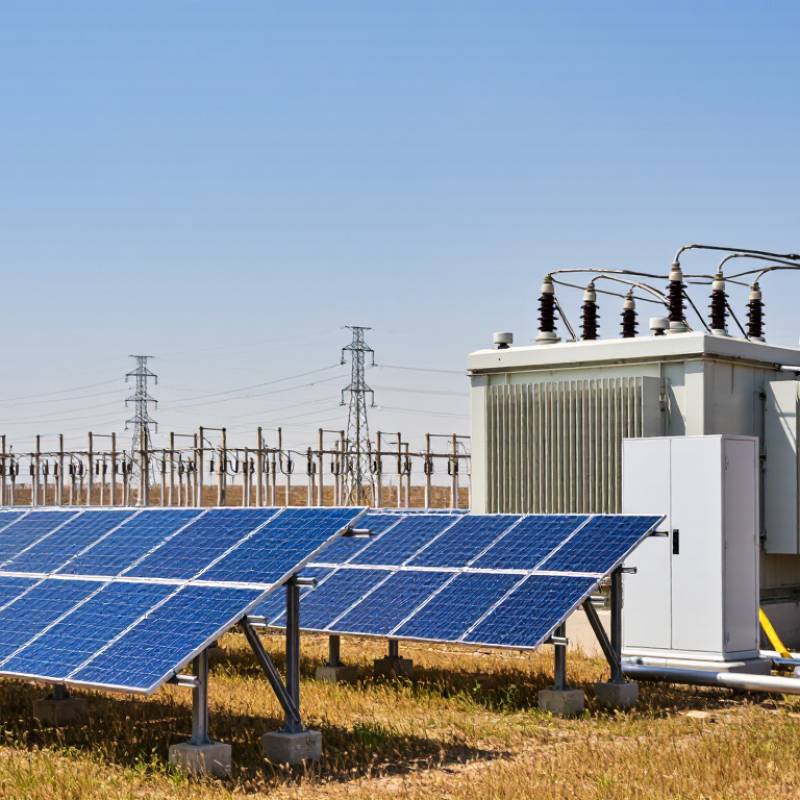
Why Are Solar Inverter Duty Transformers Important?

What Is a Solar Inverter Duty Transformer?

A solar inverter duty transformer is a specialized transformer installed between a solar inverter and the electrical grid. It raises or lowers voltage to match the grid’s requirements. More importantly, it manages the unusual electrical behavior created by modern inverters.

Solar inverters do not produce perfectly smooth waveforms. Their switching devices can create harmonics, voltage fluctuations, and rapid load changes. An inverter duty transformer is designed to handle these conditions repeatedly. Its insulation system, magnetic core, cooling method, and winding structure support dependable operation under changing solar output.

It also provides electrical isolation between the inverter and the grid. This separation can improve system protection and simplify grounding arrangements. In utility-scale projects, engineers examine impedance, temperature rise, short-circuit strength, and harmonic performance before selecting a transformer. Small design errors can cause overheating or nuisance protection trips.

The transformer must also tolerate daily cycling. Solar generation rises in the morning, peaks near midday, and falls toward evening. That pattern produces regular thermal stress. Field inspections often find that poor ventilation, loose connections, or incorrect loading shorten service life. The transformer itself may be correctly specified, yet the complete installation can still perform poorly.

The term “inverter duty” is not a universal guarantee. Specifications should be checked carefully. Project voltage, inverter technology, ambient temperature, and local grid rules all influence the final design. A transformer that works well in one solar plant may be unsuitable for another. That assumption deserves caution.

How Solar Inverter Duty Transformers Work in PV Systems

Solar inverter duty transformers connect inverter output to the medium-voltage grid in photovoltaic systems. They do more than raise voltage.

Inside a PV plant, solar modules produce direct current. Inverters convert this power into alternating current, usually at a low voltage. The transformer then increases the voltage for collection lines and grid connection. This step reduces current and limits energy loss across long cables. It also provides electrical isolation between the inverter and the grid.

The transformer then increases the voltage for collection lines and grid connection.

The operating environment can be demanding. Power changes quickly when clouds cross the array. Inverter switching creates harmonics, while outdoor heat stresses insulation and cooling systems. A properly designed transformer manages these conditions through suitable impedance, winding strength, shielding, and thermal capacity. Harmonic performance must match the inverter’s actual output, not only its data sheet.

Small details matter.

During commissioning, technicians should check phase relationships, grounding, insulation resistance, temperature sensors, and abnormal vibration. A transformer may pass factory tests yet perform poorly after installation. Cable routing, ventilation, and moisture can change its behavior. That point is easy to underestimate. Engineers should review load profiles and site conditions before selecting capacity. Oversizing can increase cost and losses, while undersizing may cause overheating during strong sunlight. Reliable operation depends on coordinated protection settings, clear maintenance records, and periodic inspection.

Key Electrical Functions and Performance Requirements

Solar inverter duty transformers connect inverter output to the collection or utility grid. They raise voltage efficiently and provide galvanic isolation between power electronics and grid equipment. Their design must handle rapid switching, harmonic currents, and frequent changes in solar production.

A suitable transformer controls voltage regulation without creating excessive losses. Low impedance can support fault performance, but it may increase fault current and mechanical stress. Insulation systems must withstand thermal cycling, switching surges, and temporary overvoltage. Temperature rise is equally important. In a hot enclosure, poor ventilation can shorten insulation life, even when the nameplate load appears acceptable. Engineers should also check acoustic noise, partial discharge, short-circuit strength, and compatibility with the inverter’s control strategy. Field measurements often reveal conditions that calculations miss.

Tips: Confirm the inverter waveform, switching frequency, grounding method, and harmonic spectrum before selecting the transformer. Review loading at sunrise, peak irradiance, and rapid cloud movement. Monitor winding temperature during commissioning. A small mismatch can become a costly problem. Do not judge performance by efficiency alone; voltage stability and thermal margin matter too. Some projects still rely on generic transformer data, which is convenient but not always reliable. Clear test records and periodic inspections provide stronger evidence of long-term performance.

Why They Matter for Grid Connection and System Safety

Why Are Solar Inverter Duty Transformers Important?
Why They Matter for Grid Connection and System Safety

Solar inverter duty transformers connect the inverter’s output to the utility grid safely and reliably. They raise voltage to the required level and provide electrical separation between equipment. This connection must remain stable during changing sunlight, switching events, and sudden load variations. A suitable transformer helps control voltage stress and supports predictable power flow.

Inverters produce fast electronic switching waveforms. These waveforms can create harmonics, heat, and extra insulation stress. Inverter duty transformers are designed with these conditions in mind. Their windings, shielding, cooling, and impedance must match the project’s operating profile. Poor matching may cause nuisance trips, overheating, or unstable grid performance. Small details matter.

Grounding and fault protection are equally important. The transformer helps define the system’s grounding arrangement and limits certain fault currents. Engineers still need correctly coordinated breakers, surge protection, monitoring, and emergency isolation. A transformer is not a magic shield. Installation quality matters too. Loose connections, blocked ventilation, or incorrect settings can weaken an otherwise sound design. During commissioning, technicians should verify phase sequence, insulation resistance, temperature behavior, and protection responses. Field conditions sometimes expose assumptions that looked reasonable on paper. That is where careful testing and documented maintenance become essential.

Why Are Solar Inverter Duty Transformers Important? — Why They Matter for Grid Connection and System Safety
Technical Dimension Typical Data or Design Range Importance for Grid Connection Safety and Verification Considerations
Primary Function Steps inverter output voltage up from low voltage, commonly 0.4–1.5 kV, to a medium-voltage collection or utility connection level, commonly 10–35 kV. Matches the solar plant voltage with the collector system or utility interconnection voltage, reducing current and distribution losses. Confirm primary and secondary voltage ratings, insulation coordination, grounding arrangement, and utility interconnection requirements.
Rated Power Common project ratings range from approximately 1 MVA to more than 10 MVA per transformer, depending on inverter configuration and plant size. Determines how much active and reactive power can be transferred without excessive thermal loading or voltage drop. Select continuous and short-time ratings using inverter output, ambient temperature, altitude, harmonics, overload requirements, and future operating conditions.
System Frequency 50 Hz or 60 Hz, selected to match the local electrical grid. A frequency mismatch can prevent synchronization and may cause abnormal flux, overheating, or protection operation. Verify the transformer frequency rating against the inverter, grid code, and commissioning test plan.
Transformer Impedance Approximately 5%–10% is common for many medium-voltage power-transformer applications; the final value is project-specific. Influences voltage regulation, fault current, reactive-power behavior, and parallel-transformer load sharing. Coordinate impedance with inverter controls, switchgear interrupting capacity, protection settings, and acceptable voltage variation.
Vector Group and Grounding Common arrangements include a grounded-wye connection on the grid side and a delta or wye connection on the inverter side, subject to system design. Controls phase displacement, zero-sequence current paths, triplen-harmonic behavior, and the way ground faults are detected. Verify phase displacement, neutral grounding method, ground-fault protection, and compatibility with the inverter output transformer requirements.
Insulation Level Specified by the system voltage and insulation-coordination study; medium-voltage equipment may use impulse withstand levels such as 95 kV or 125 kV for selected voltage classes. Provides adequate protection against lightning impulses and switching surges on the collector or utility network. Coordinate basic insulation level, surge arresters, clearances, creepage distances, and cable termination ratings.
Harmonic Loading Inverter-generated current distortion is controlled by the inverter design and grid-code limits; transformer heating can increase even when RMS current is within its fundamental rating. Excess harmonics can increase losses, affect voltage quality, create resonance risks, and interfere with protection or metering. Review harmonic spectrum, K-factor or equivalent thermal capability, stray-loss heating, and the results of a power-quality study.
Cooling and Temperature Rise Dry-type or liquid-immersed cooling may be used. Temperature-rise limits are established by the applicable transformer standard and design class. Adequate cooling maintains available capacity during high solar irradiance and helps prevent derating during peak generation. Account for enclosure ventilation, ambient temperature, solar exposure, altitude, fire protection, fluid containment, and thermal alarms.
Voltage Regulation Typically designed to keep secondary voltage within the inverter and grid interconnection operating range under changing load and reactive-power conditions. Stable voltage supports inverter ride-through, reactive-power control, and compliance with the permitted point-of-common-coupling voltage range. Perform load-flow studies at minimum and maximum generation, including reactive-power export or absorption and tap-position limits.
Short-Circuit Withstand The transformer must withstand the prospective fault current for the specified clearing time without unacceptable mechanical or thermal damage. Supports safe fault clearing and prevents a transformer fault from escalating into a wider collection-system outage. Coordinate transformer withstand capability with upstream and downstream breakers, fuses, relays, grounding impedance, and clearing times.
Protection Functions Typical functions include overcurrent, earth fault, overtemperature, differential protection for larger units, and surge protection. Disconnects abnormal conditions quickly while minimizing unnecessary trips during normal inverter transients and grid disturbances. Validate relay curves, trip coordination, transformer inrush restraint, alarm stages, and communication with the plant control system.
Standards and Testing Common reference standards include IEC 60076 for power transformers, IEEE C57.12.00 for general transformer requirements, and applicable local grid codes. Provides a consistent basis for ratings, insulation, losses, temperature rise, dielectric tests, and grid-connection acceptance. Review routine and type-test documentation, ratio and polarity tests, winding-resistance tests, insulation tests, functional protection tests, and site commissioning records.
Efficiency and No-Load Loss Transformer losses consist mainly of no-load losses and load-dependent losses; actual efficiency depends on rating, loading profile, voltage, and design. Lower losses improve annual energy yield and reduce the thermal burden on the solar plant’s collection system. Compare guaranteed losses with the plant load profile and verify that loss measurements follow the specified test standard.
Audible Noise Noise limits are normally specified in decibels at a defined distance and operating condition; the permitted value depends on site requirements. Noise performance can affect the location of inverter-transformer stations near residences, offices, or environmentally sensitive areas. Include enclosure design, cooling equipment, mounting, vibration isolation, and site noise measurements in the acceptance criteria.
Service Life and Maintenance A properly specified and maintained power transformer is commonly designed for several decades of service, subject to loading, temperature, environment, and insulation aging. High availability reduces energy losses caused by prolonged outages and supports predictable plant operation. Use scheduled inspections, thermal monitoring, connection checks, insulation assessment, oil testing where applicable, and condition-based maintenance.
Note: The numerical ranges shown are typical engineering reference values, not universal specifications. Final ratings and settings must be confirmed through the project load-flow, short-circuit, harmonic, grounding, insulation-coordination, and grid-code studies.

Factors to Consider When Selecting One for a Solar Project

Why Are Solar Inverter Duty Transformers Important?

Selecting an inverter duty transformer requires more than matching the inverter’s nameplate kVA. Solar inverters create switching harmonics, rapid load changes, and occasional reverse power flow. These conditions can increase winding losses and temperature. The IEA PVPS Trends 2024 report recorded more than 400 GW of new solar capacity worldwide in 2023. That scale makes transformer reliability a practical project concern, not a minor specification detail.

Engineers should check continuous rating, overload capability, voltage ratio, impedance, and vector group. A transformer with excessive impedance may restrict fault performance and voltage regulation. A low value may increase fault current. IEEE C57.91 provides methods for evaluating transformer loading and thermal aging. Harmonic studies should also guide the design, especially when many inverters share one medium-voltage collector circuit. Do not rely only on standard utility data.

Site conditions matter. High altitude, dust, humidity, salt air, and ambient temperatures can reduce cooling performance. IEC 60076 supports the evaluation of insulation, temperature rise, and testing requirements. For outdoor projects, enclosure protection and corrosion resistance deserve close inspection. Dry-type units can simplify spill-risk management, while oil-filled units may offer useful thermal performance. The better choice depends on access, maintenance skills, and fire planning. In practice, project teams sometimes undersize transformers to reduce capital cost. That decision can look efficient, but repeated thermal stress may shorten service life. A detailed loss estimate, harmonic model, and maintenance plan should come before procurement.

FAQS

What is a solar inverter duty transformer?

It connects a solar inverter with the electrical grid. It adjusts voltage for grid requirements. It also handles changing electrical conditions.

Why does a solar project need this transformer?

Inverters can create harmonics, voltage changes, and rapid load shifts. The transformer manages these stresses repeatedly. It also provides electrical separation.

How does daily solar production affect transformer operation?

Output usually rises in the morning, peaks near midday, and falls in the evening. This cycle creates repeated thermal stress. Heat matters.

Which technical details should engineers check?

They should review continuous rating, overload capability, voltage ratio, impedance, and vector group. Short-circuit strength also matters. Nameplate kVA alone is insufficient.

How can harmonics influence transformer selection?

Harmonics can increase winding losses and operating temperature. A harmonic study helps estimate these effects. Several inverters sharing one circuit may increase concern.

Do site conditions change the transformer design?

Yes. High altitude, dust, humidity, salt air, and heat can reduce cooling performance. Outdoor equipment may need stronger enclosures and corrosion protection. The site is part of the design.

Should a project use a dry-type or oil-filled transformer?

Dry-type units may simplify spill-risk management. Oil-filled units can provide useful thermal performance. Access, maintenance skills, and fire planning should guide the choice.

Can a correctly specified transformer still perform poorly?

Yes. Poor ventilation, loose connections, or incorrect loading can shorten service life. The installation may be the weak point. That possibility deserves attention.

Is “inverter duty” a complete performance guarantee?

No. The term does not define every operating condition. Project voltage, inverter design, temperature, and grid rules still matter. A suitable choice requires careful specification review.

Conclusion

Solar Inverter Duty Transformers are specialized transformers designed to connect solar inverters with medium- or high-voltage electrical networks. In a photovoltaic system, they receive the inverter’s converted AC power, adjust the voltage to the required level, and provide electrical isolation between the generation equipment and the grid. Their design must accommodate variable solar output, frequent load changes, harmonic currents, and the operating conditions created by modern power-electronic inverters.

These transformers are important because they support stable power transfer, efficient voltage conversion, and safer grid interconnection. Strong insulation, suitable thermal capacity, low losses, dependable impedance, and resistance to harmonic stress are key performance requirements. When selecting a unit for a solar project, engineers should evaluate its rated power, voltage ratio, cooling method, environmental conditions, installation location, protection requirements, maintenance needs, and compatibility with the inverter and grid. Choosing the right transformer can improve system reliability, reduce energy losses, support long service life, and help the entire PV plant operate safely and consistently.

Amelia

Amelia

Amelia is a professional marketing specialist with a strong understanding of product strategy, customer needs, and digital communication. As a key contributor to the company’s content and marketing initiatives, she regularly publishes insightful articles on the company website, helping readers......